DIY Cessna 172 Radio stack
Work in progress . . .
|
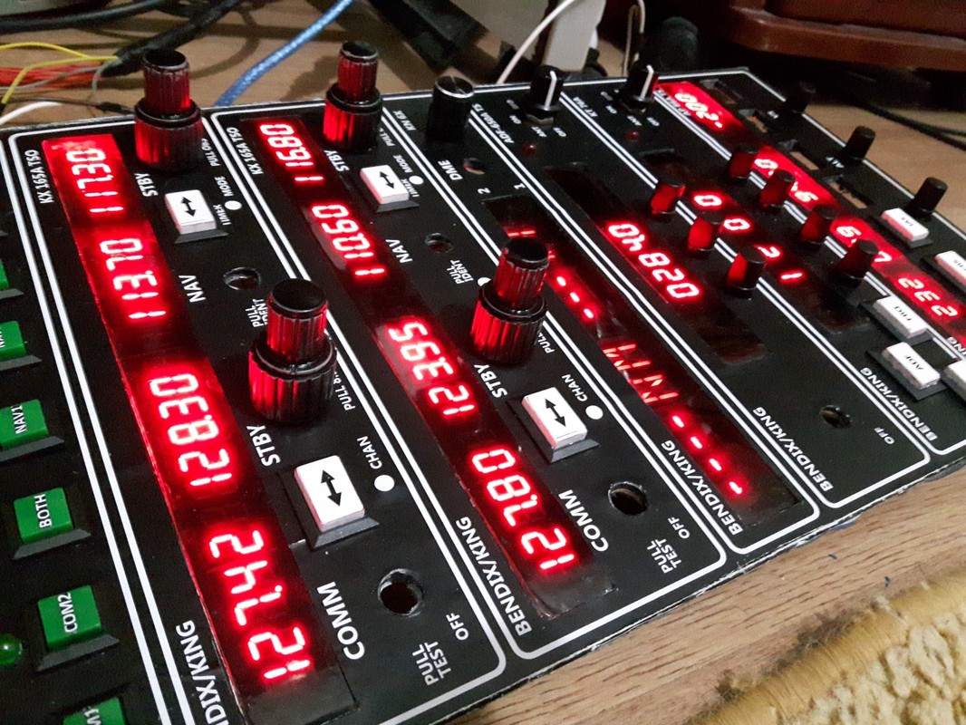
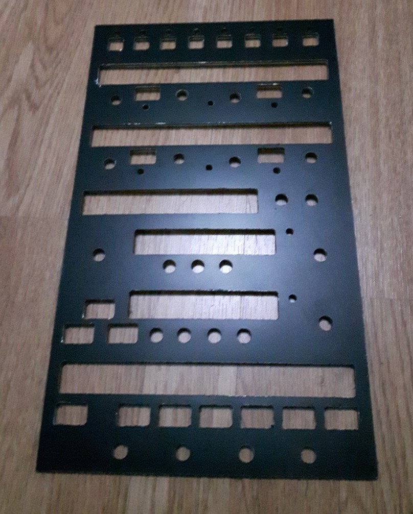
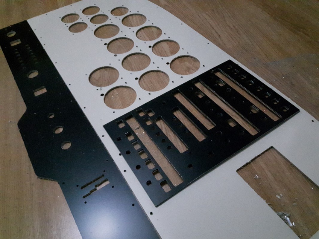
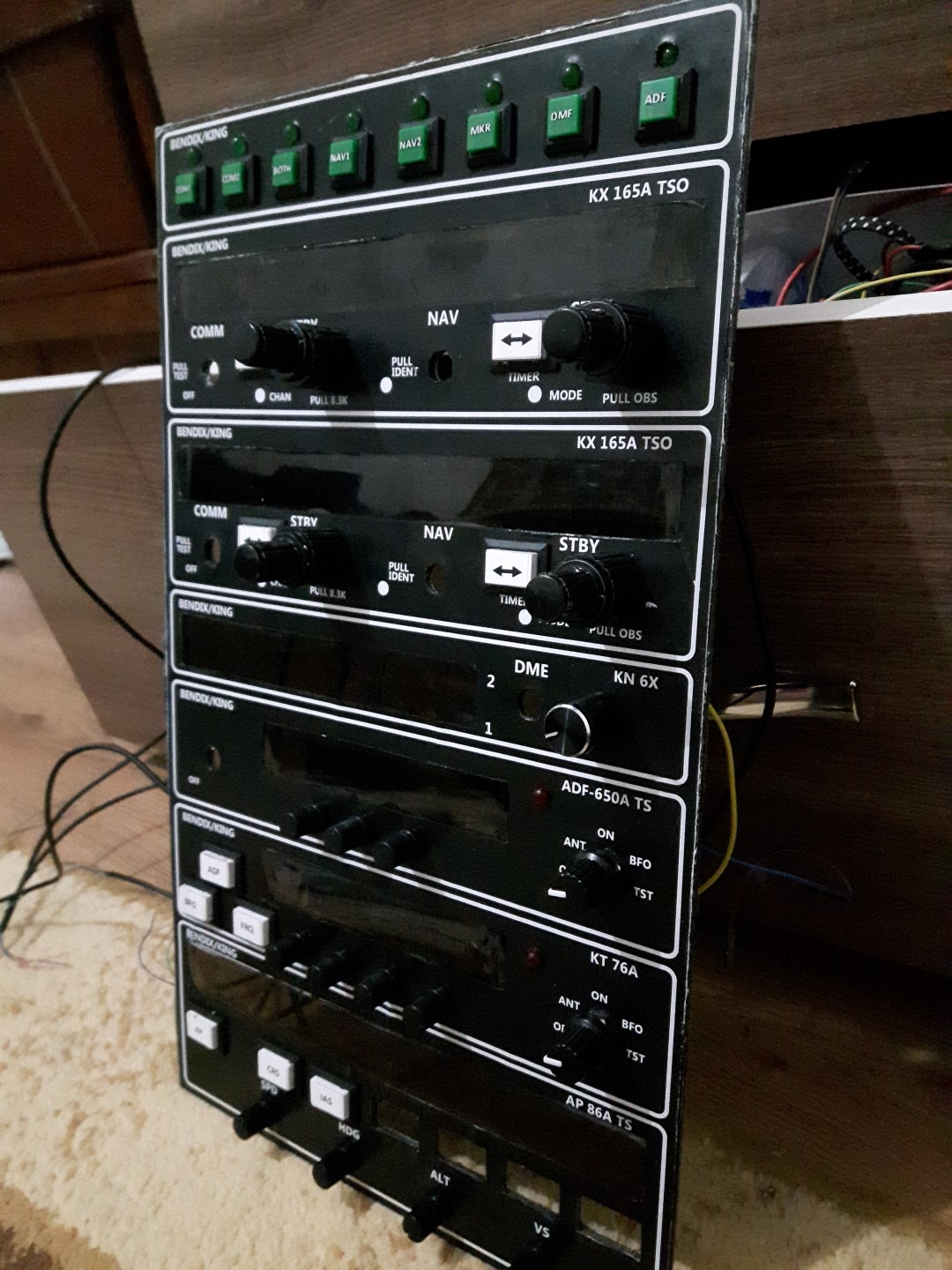
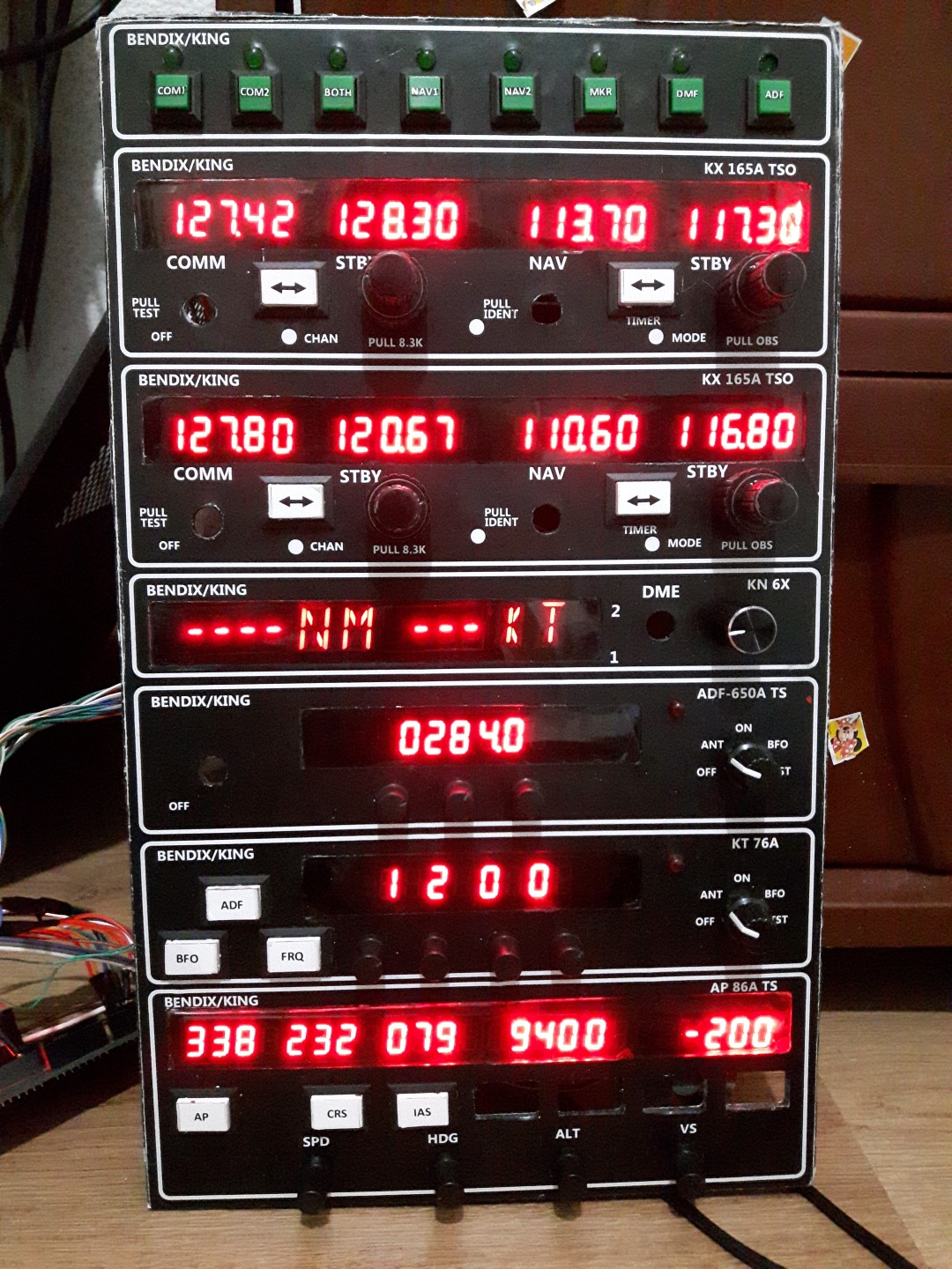
If some of you don't want to go with the PCB version of the radio stack, you can start building it yourself with this DIY version. First i wanted to go with a 19 inch screen to simulate the radios, but it is surely better to make a more realistic looking radio, that's why i decided to build it myself using 7 segment displays, an arduino mega 2560 and a software called Mobiflight (respect to the author for this great software). Mobiflight is a free, easy to use software that allows you to extract and send data from FSX, Prepar3D ore X-Plane to your Arduino board. It offers a lot of options without the need to know arduino programming. There are some preset options but you can input the fsuipc offset and the sofware uploads the code to your card. For more info and tutorials on how to use Mobiflight, please visit the website. |
|
What I used:
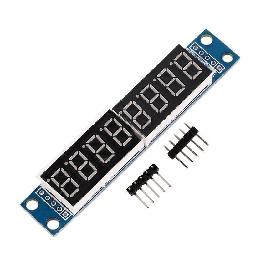
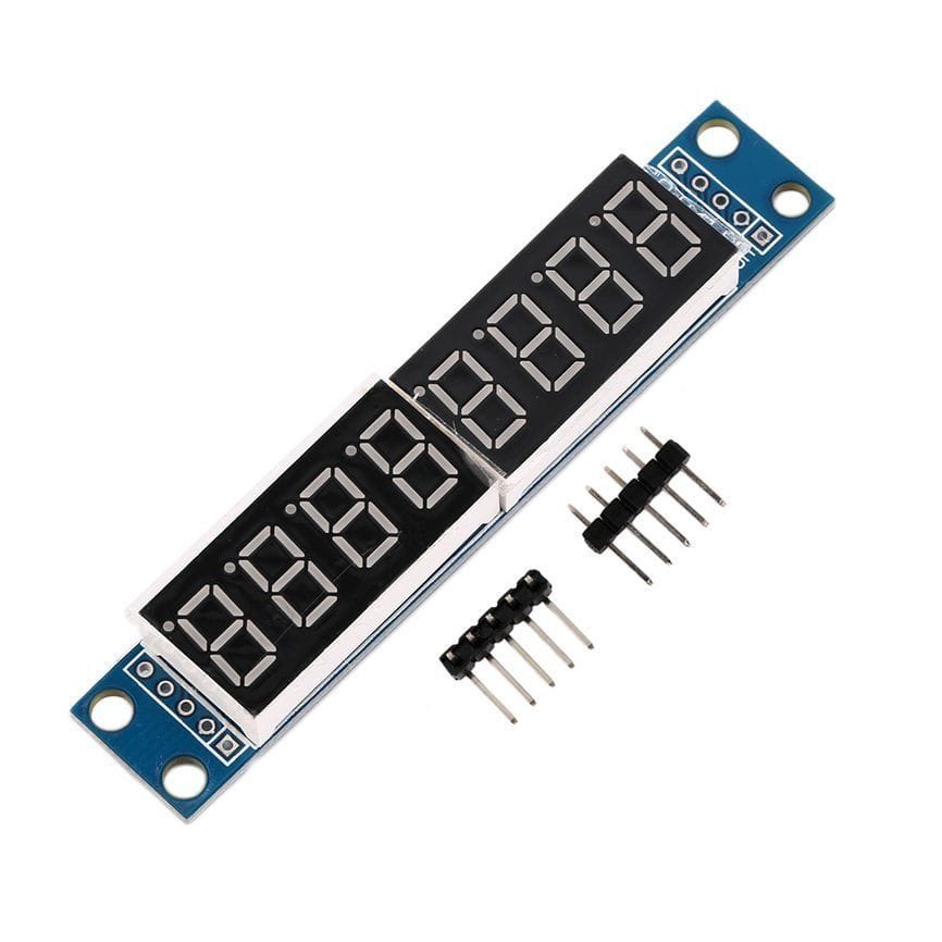
- Max7219 8-Digit 7 Segment Displays - $ 19.8 (12 Pcs)
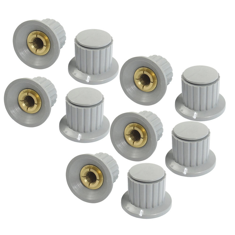
- Volume Control Knob 6mm - $ 7.24 (10Pcs)
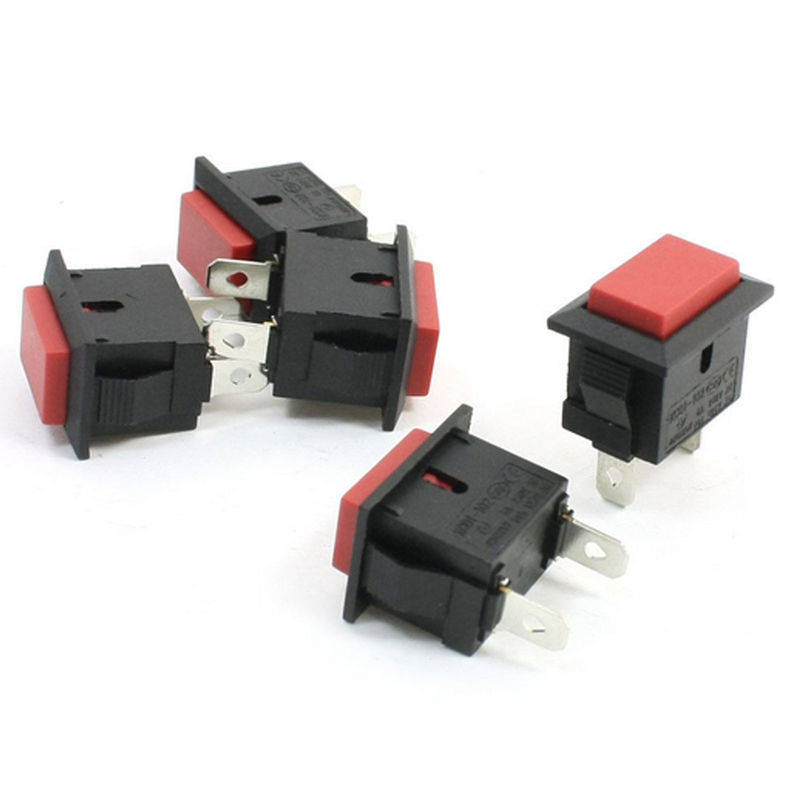
- Red Cap Rectangle SPST Push Button - $ 8.46 (15 Pcs)
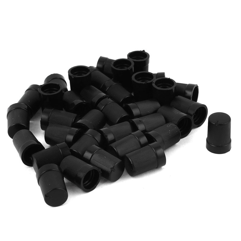
- Black Plastic Knob - $ 3.42 (35 Pcs)
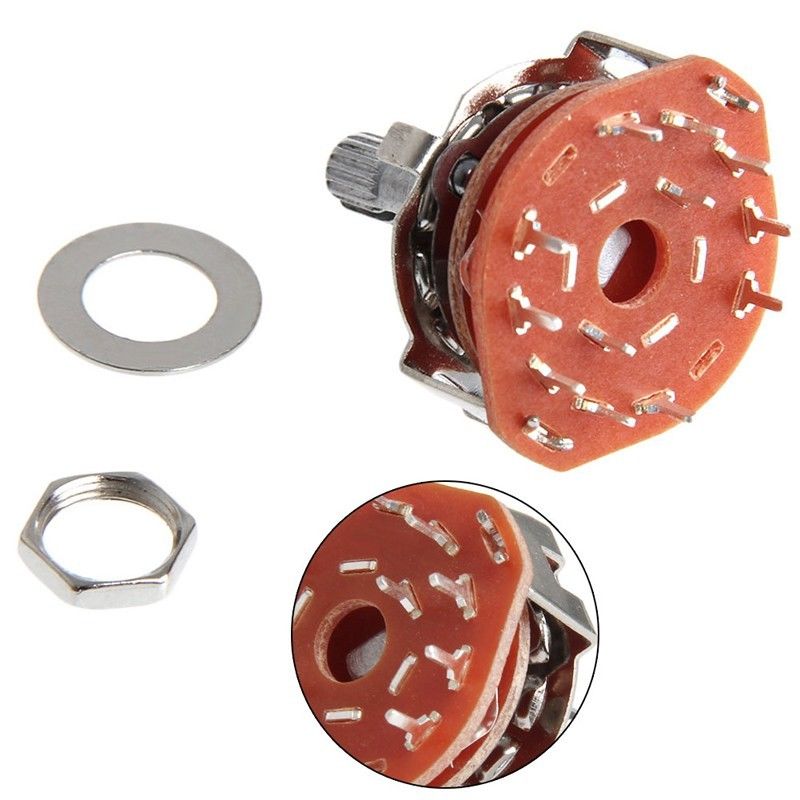
- 2P5T Rotary Switch - $ 2.72 (3 Pcs)
|
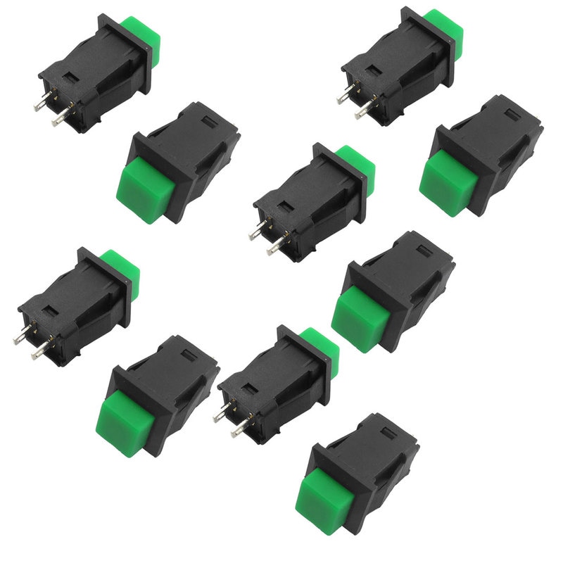
- Green Square Cap SPST Switch - $ 3.17 (10 Pcs)
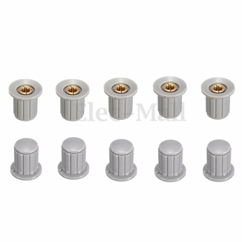
- Insert Tone Core Brass Knob - $ 3.15 (10 Pcs)
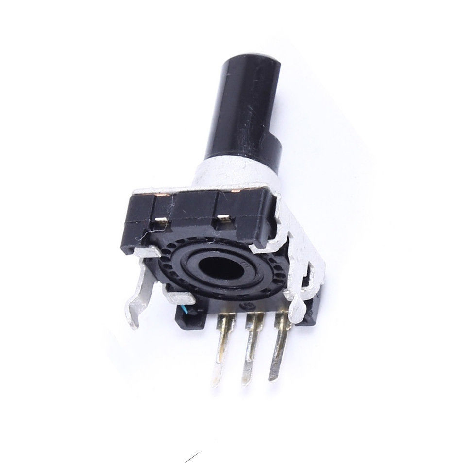
- Rotary Encoder EC12 - $ 5.05 (20Pcs)
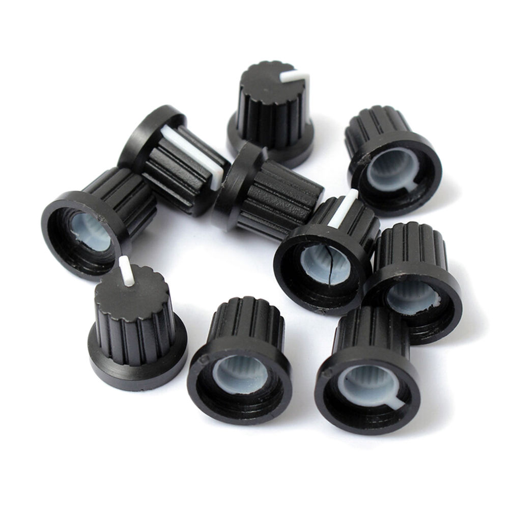
- Threaded Knurled Knobs - $ 0.86 (10 Pcs)

| ||
|
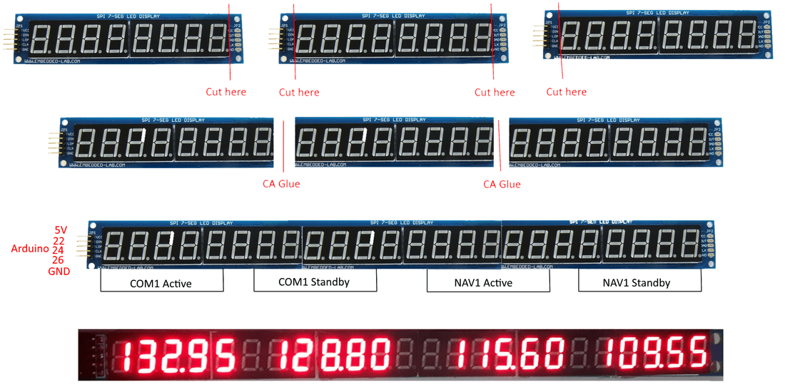
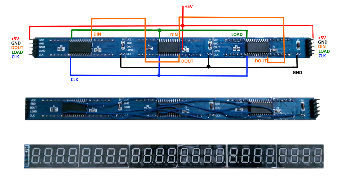
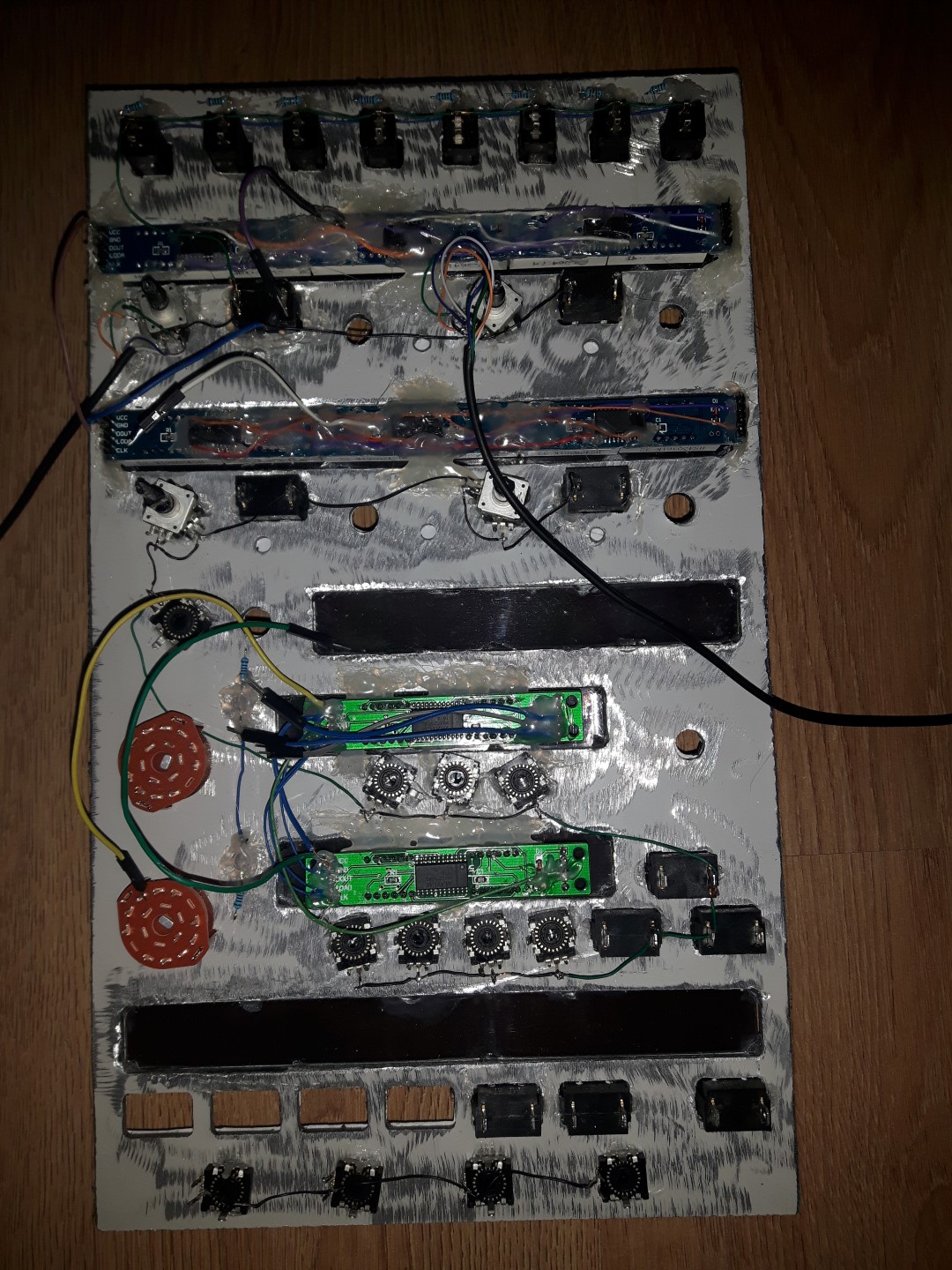
The first thing we need are the 7 segment displays. Mobiflight supports Max7219 8-Digit 7 segment displays which are very cheap, and you can connect them in series. The only problem is that between two displays there is a space. What i did was cuting the sides with a knife, glued them together with CA Glue and soldered the connections on the back. Since the radio has 5 digits for each COM and NAV, i needed 20 digits in total, 2 spaces between Active and Standby and one space of two digits between COM and NAV, which makes it 24 digits in total. That means i had to connect three Max7219 displays together to get 24 digits. |
|
|
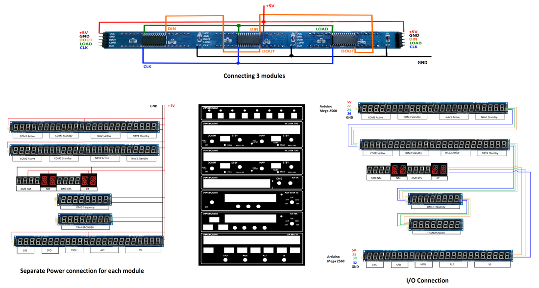
From the picture above you can see the difference in intensity of the displays as you go from left to right. This is due to inadequate power tracking along the boards as they are connected in serial. I will power the boards separately to avoid this. The picture above is done for testing purpose. After cutting, glueing and soldering the boards (I will post pictures of the backside how to connect them in series), connect them as in the picture above, VCC on 5V, GND - GND, and three following pins to Arduino port 22, 24, 26 accordingly.
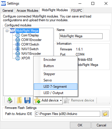
Once connected, plug in the Mega to PC and open up Mobiflight. Go to Mobiflight Modules and click on MobiFlight Mega. Click on the Add device button select LED 7-Segment.
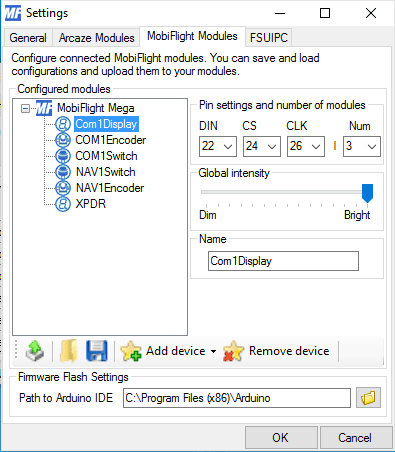
Select the newly added display and choose arduino pins (i have chosen 22, 24, 26 and 3 is the number of displays. Choose the desired intensity of display and name the display (I named it Com1Display). Save the settings and click the button with the arrow pointing up to upload the sketch to your arduino.
Once the upload is done, double click on the first row and name it Com1Active. We are going to add five digits and one dot for the COM 1 Active frequency.
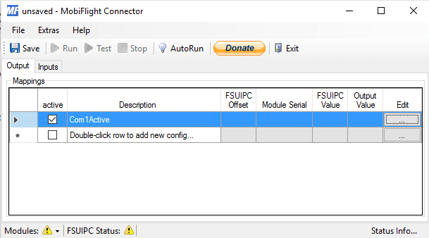
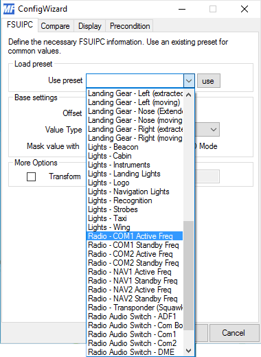
Click on the three dots on the edit column and on the next window under FSUIPC tab open the preset options scroll down and choose Radio-COM1 Active Freq.
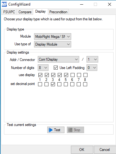
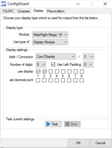
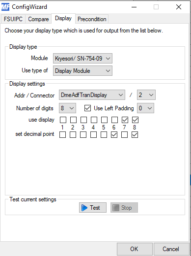
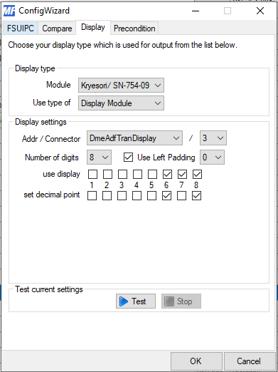
Now go to Display tab , click on module and choose MobiFlight Mega/...., under Use type of choose Display Module. Addr/Connector is going to be Com1Display. We have 3 displays connected together so for the first 5 digits we are going to use display 1 that's why we choose number 1 as the next option. Number of digits 8 and Use Left Padding checked and choose 0. Now check first five digits and on the second row set the decimal point on number three.
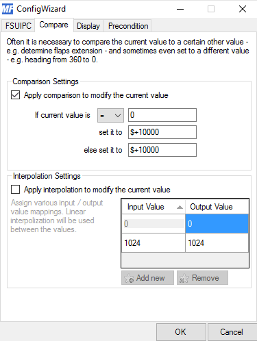
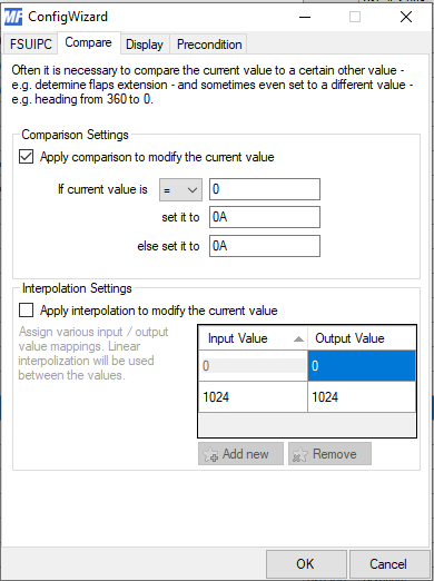
Under Compare tab check Apply comparison to modify the current value and set as in the picture below. If current value is = 0 than set it to $+10000 else set it to $+10000
Click OK and you are done with COM 1 Active Freq. If you click Run, COM 1 Active frequency will display on your 7 Segment Display. Do the rest as below and set frequencies for COM 1 Active, COM 1 Standby, NAV 1 Active and NAV 1 Standby.
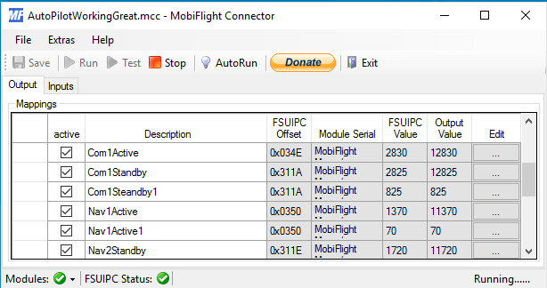
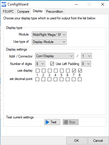
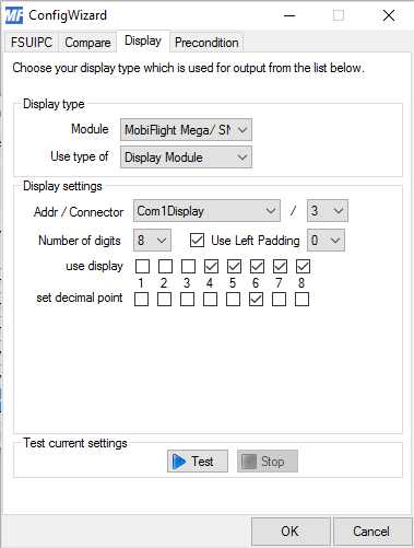
Name the second row Com1Standby, under FSUIPC presets choose COM1 Standby Freq, under Compare the same as above and under Display choose Com1Display 1 and choose digits 7 and 8 (first picture below).
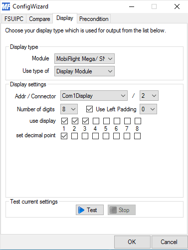
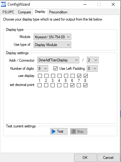
The third row is Com1Standby1 because we are going to display the rest 3 digits on our 2nd display. To do this like before under FSUIPC choose COM1 Standby Freq, under Compare the same as above and under Display choose Com1Display 2 and choose first three digits and set the decimal point on the first square (second picture below).
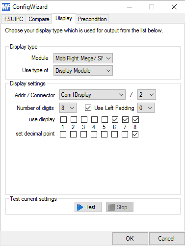
Do accordingly for the rest of the frequencies by looking at the pictures below.
Fourth row - Picture 3, Fifth row - Picture 4 and Sixth row - Picture 5.
|
|
|
|
|
After you are done with all the frequencies, open up FSX, start a flight and click Run on Mobiflight, congratulations you have COM 1 and NAV 1 displayed on your 7 Segment display module.
Do the same with the second display for COM 2 and NAV 2. Connect both display tubes in series and now you have to replace the order where the numbers should be shown. For COM2 Active start with Addr/Connector Com1Display and module number 4 and so on. You can download below a config file of my mobiflight configuration of my Mega2560. First flash open MobiFlight, load mobiflight_mega.mfmc and upload the firmware to your ArduinoMega 2560 then open MobiflightConfig.mcc and select your corresponding card and the appropriate input/output. This is a work in progress so the files will be updated. All these files are included in the "radiostack.zip" file above. To download the files below, right click on Download File and then click on "Save link as...".
NM and KT
|
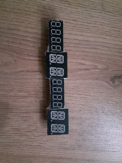
The next challenge was to recreate the NM and KT letters on the DME. There are two ways to do this, based on the method I'm using (using Max7219 modules). The first method would be the easiest which is to print the letters KT and NM on a transparent sheet and use red leds behind them to light them. The second method is using 14 segment displays. It is a bit more complicated but since I already had those displays I wanted to try it out.
|
|
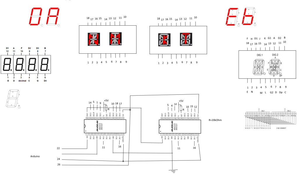
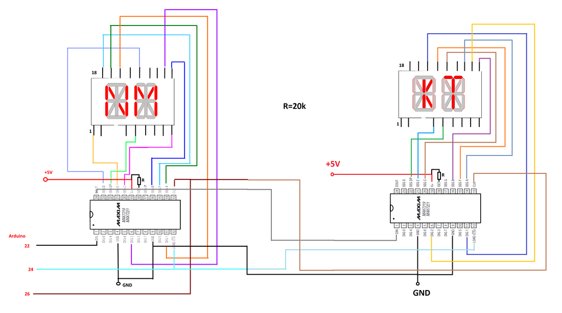
The idea was to use Max7219 chips so I could connect them in series with other modules on the radiostack and I also wanted to be controlled with mobiflight. I used 2x Max7219 chips and daisy chained them with other modules of the radiostack. You need 2x 2digit 14 segment displays and two Max7219 modules. The connection is easy. You just follow the above schematic. Connect the pin number of the Max7219 module the the corresponding number of the 14 segment display. After completing the connection, all you have to do is on the Mobiflight, on the condition field to use A0 to display NM and bE to display KT.
|
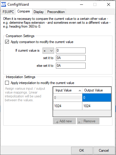
NM - 0A
|
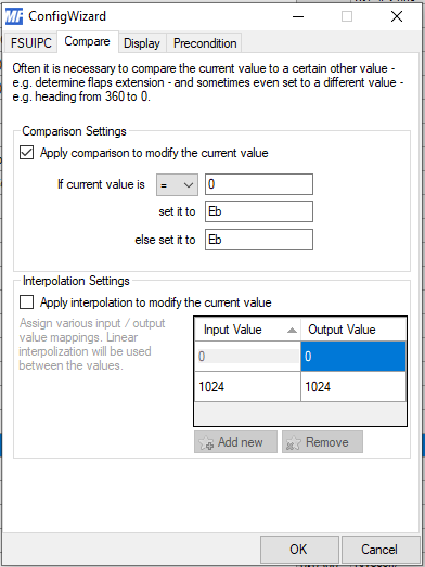
KT - Eb
|
|
|
|
Here you can download a more detailed explanation.
|

| ||
|
|
|
|
|
|
2015, Copyright AlbEAGLE