Radio stack - PCB Version
(Radio Stack Gerber files)
|
Update 20.02.2023 : I have decided to post the Gerber files for the Radio Stack, Arduino Shield, GPS as well as all downloadable files on a separate site. For all the time I have been working on it, i will be charging a small amount of money for the files, the prices you will find on the other site called "Downloads" ( I didn't do all this work for money but money is still needed to buy all the components and all this work is time consuming ). Only for personal use, if you want to use it commercially you need to contact me first.
The radio is working. Please check Radio components below before purchasing PCB. |
|
Radio stack V3.2.1
Update June 2024
Changes:
1. Changed NAV 1 Encoder pin 13 to 32
2. Pin 13 is now for Transponder OFF
2. Removed AP encoder switches (they are not needed anyway)
1. Changed NAV 1 Encoder pin 13 to 32
2. Pin 13 is now for Transponder OFF
2. Removed AP encoder switches (they are not needed anyway)
Radio stack V3.2
Update January 2024
Changes:
1. Fixed 74HC165 Inputs
2. Fixed Encoder/Potentiometer push buttons
3. Changed Com1, Nav1, Com2, Nav2 encoders to Potentiometers.
4. Enlarged the Ident and AP button holes.
5. Added +/- signs to the buttons with LED's
*There are few mistakes in V3.1, those that have purchased V3.1 please check the Forum for the fix, or if you want just ask for V3.2 for free.
1. Fixed 74HC165 Inputs
2. Fixed Encoder/Potentiometer push buttons
3. Changed Com1, Nav1, Com2, Nav2 encoders to Potentiometers.
4. Enlarged the Ident and AP button holes.
5. Added +/- signs to the buttons with LED's
*There are few mistakes in V3.1, those that have purchased V3.1 please check the Forum for the fix, or if you want just ask for V3.2 for free.
Here is a picture of the Radio stack V3.2 working with MSFS 2020
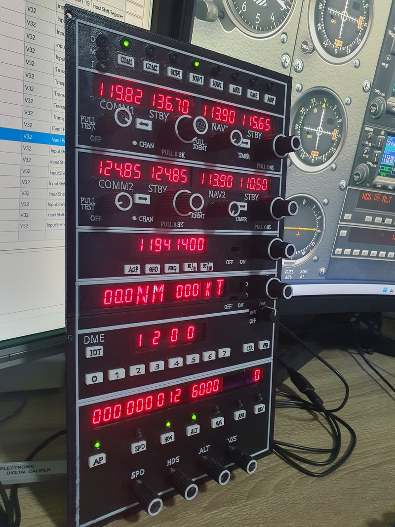
A short video demonstrating the functionality of the Radio stack V3.2 working with MSFS 2024
|
|
Working well with MSFS 2020
|
|
A little transponder update
|
|
And here is a video demonstrating Radio stack V3.2 working with X-Plane
|
|

|
| ||||
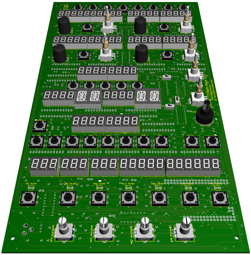
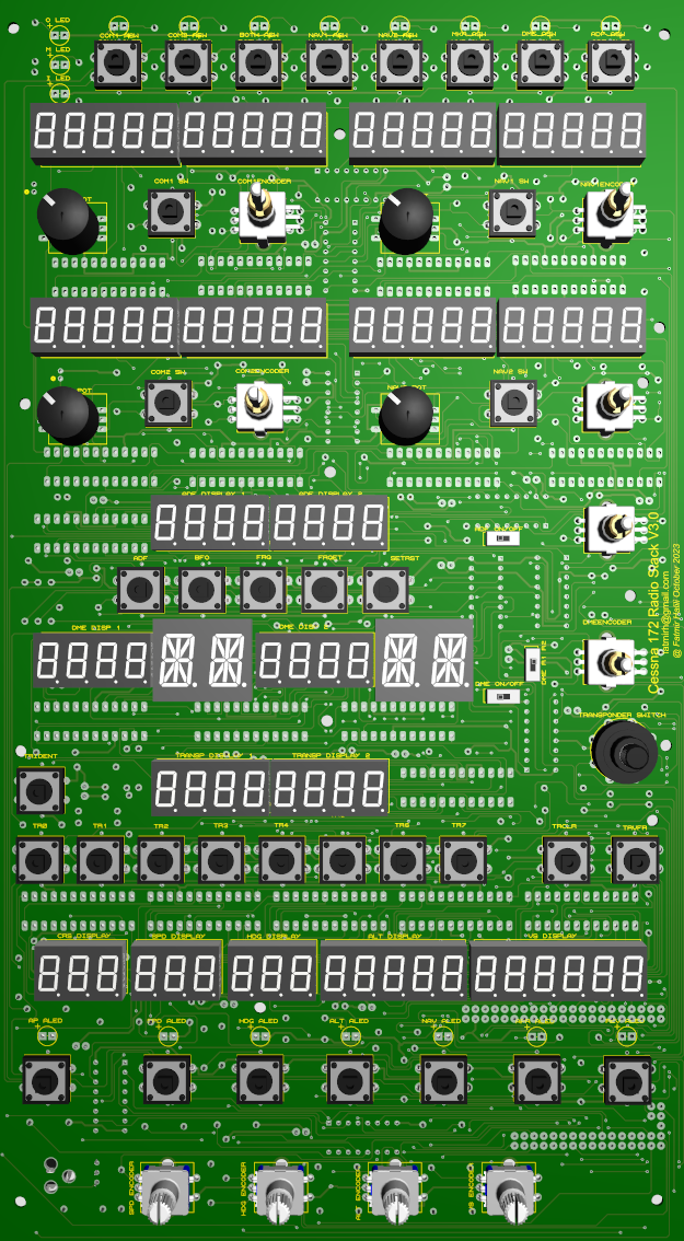
Radio stack V3.1
Update October, 2023
Changes:
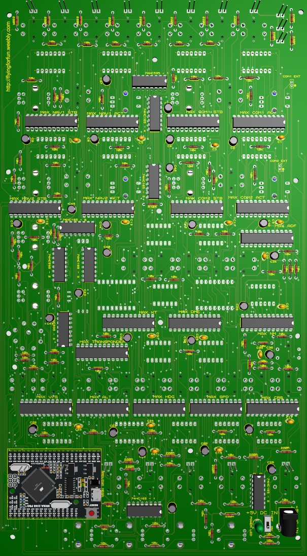
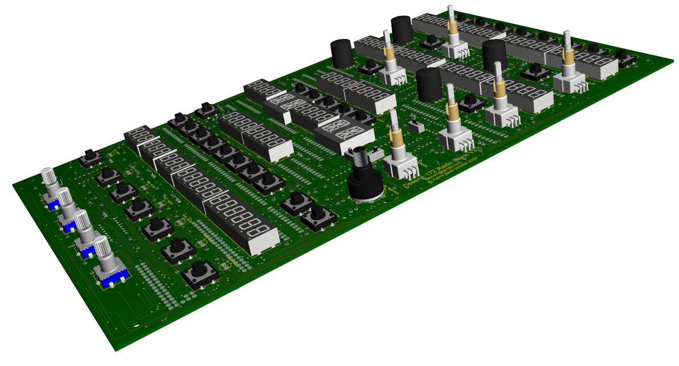
1. Arduino Mega 2560 directly attachable to the back of the PCB (only one Arduino Mega 2560 Pro (small arduino) needed, no need for Arduino shield).
2. Added input shift registers (74HC165) for the push buttons, the number of Arduino pins reduced a lot.
3. Added output shift registers (74HC595), all LEDs are now handled through 74HC959 shift registers, supplied externally with +5V, no current drawn from Arduino
4. Replaced the Transponder rotary switch with a smaller one.
1. Arduino Mega 2560 directly attachable to the back of the PCB (only one Arduino Mega 2560 Pro (small arduino) needed, no need for Arduino shield).
2. Added input shift registers (74HC165) for the push buttons, the number of Arduino pins reduced a lot.
3. Added output shift registers (74HC595), all LEDs are now handled through 74HC959 shift registers, supplied externally with +5V, no current drawn from Arduino
4. Replaced the Transponder rotary switch with a smaller one.
|
|
|
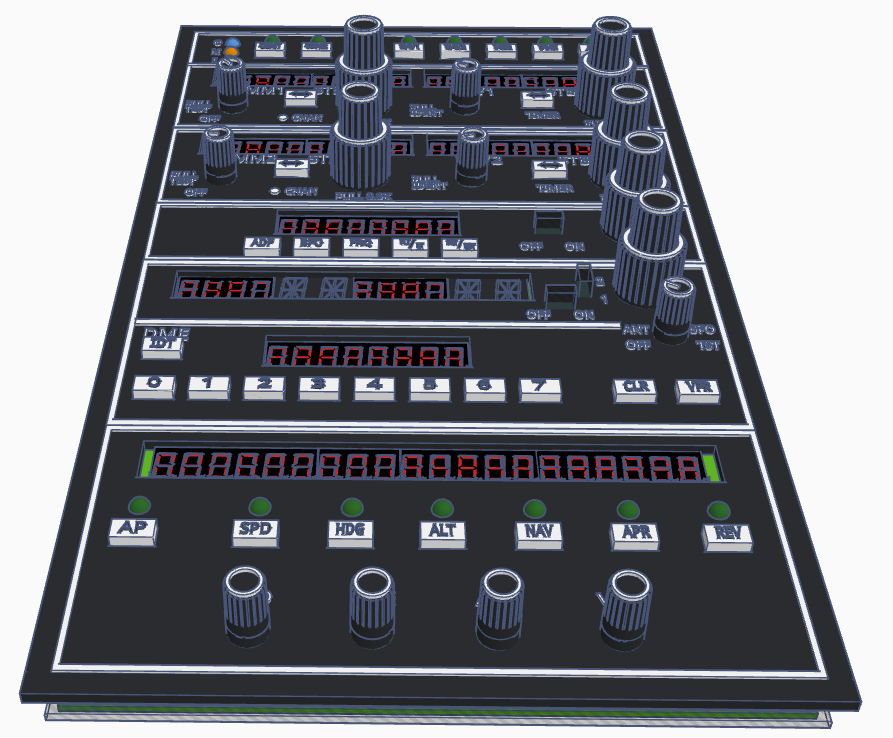
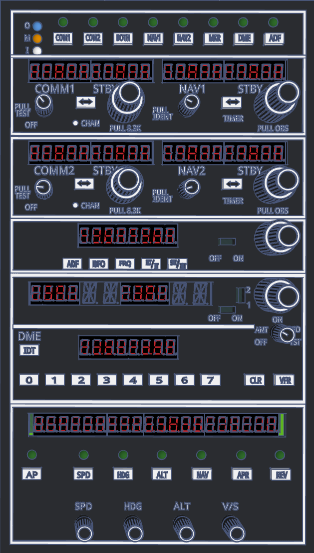
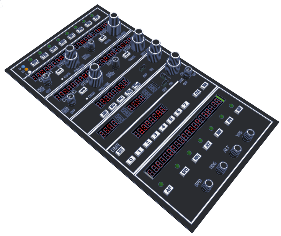
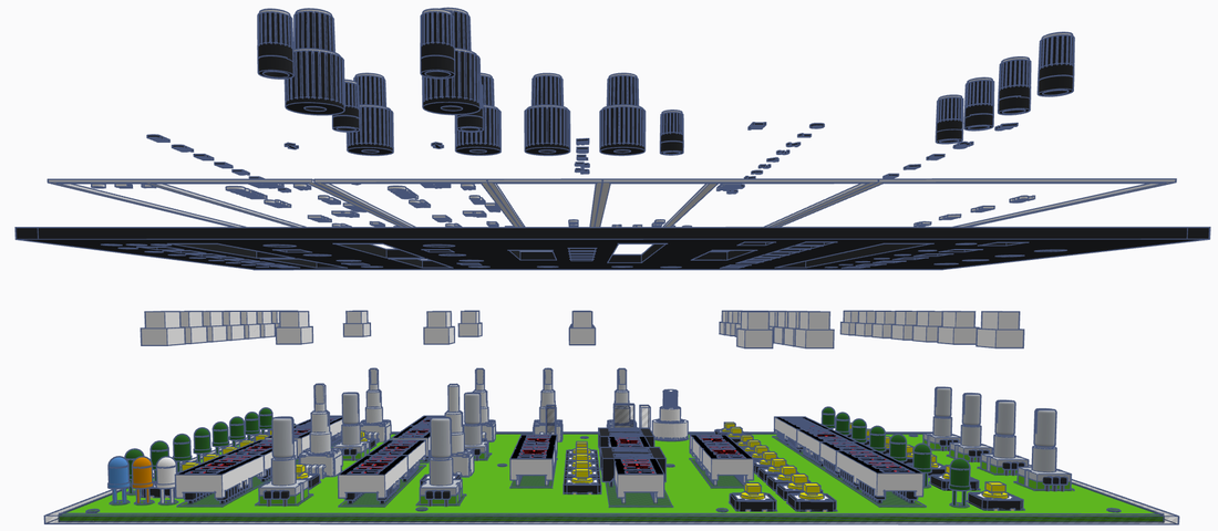
Radiostack V3.xx Faceplate
The faceplate will work for V3.1 and V3.2
|
|
|
Radio stack V2.2
Update March, 2023
Changes:
1. Replaced DIY dual encoders with EC11EBB24C03 dual encoders
2. Added GND to the first Arduino shield (Arduino shield V2.2)
You can require the gerber files on the Downloads site.
1. Replaced DIY dual encoders with EC11EBB24C03 dual encoders
2. Added GND to the first Arduino shield (Arduino shield V2.2)
You can require the gerber files on the Downloads site.
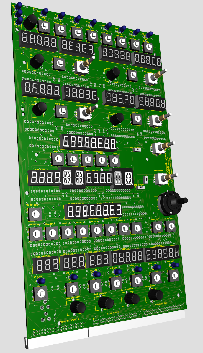
Pinouts looking from the back of the Radiostack.

Radio stack V2.1
Update November, 2020
|
I have found some free time lately and I have done some fixes in the Radiostack.
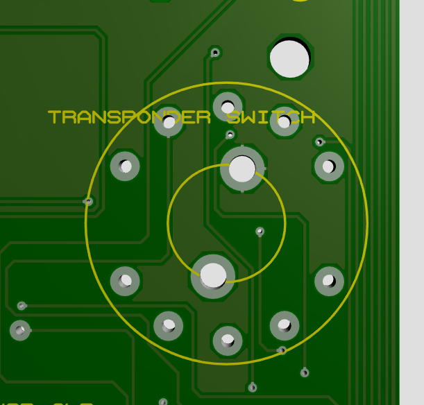
Changes: 1. Fixed the Transponder 5 pin switch alignment, now the 5 position switch should fit in place 2. Fixed GND Pin issue in the Encoder, Switches and Leds connections 3. Moved Nav2Mhz+- and Nav2Khz+- to Card2, moved DmeKhz+- to Card3 4. AP Alt GND is also connected. 3. Radiostack pins aligned with Arduino Shield pins. 4. The rest of arduino ports usable now You can require the gerber files on the Downloads site. |
|
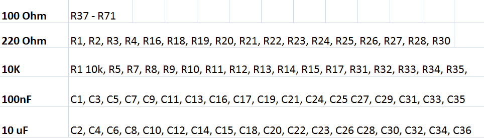
Use below pictures as reference to solder the resistors (click on the picture to zoom in). As the capacitors are only two types, it is easy to solder them based on their shape.
or download below for better quality
or download below for better quality

| radiostack_v2.1_reistor_values.rar |
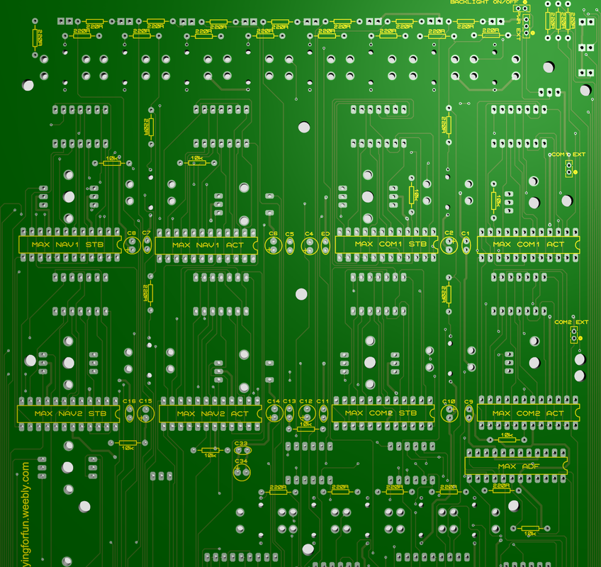
|
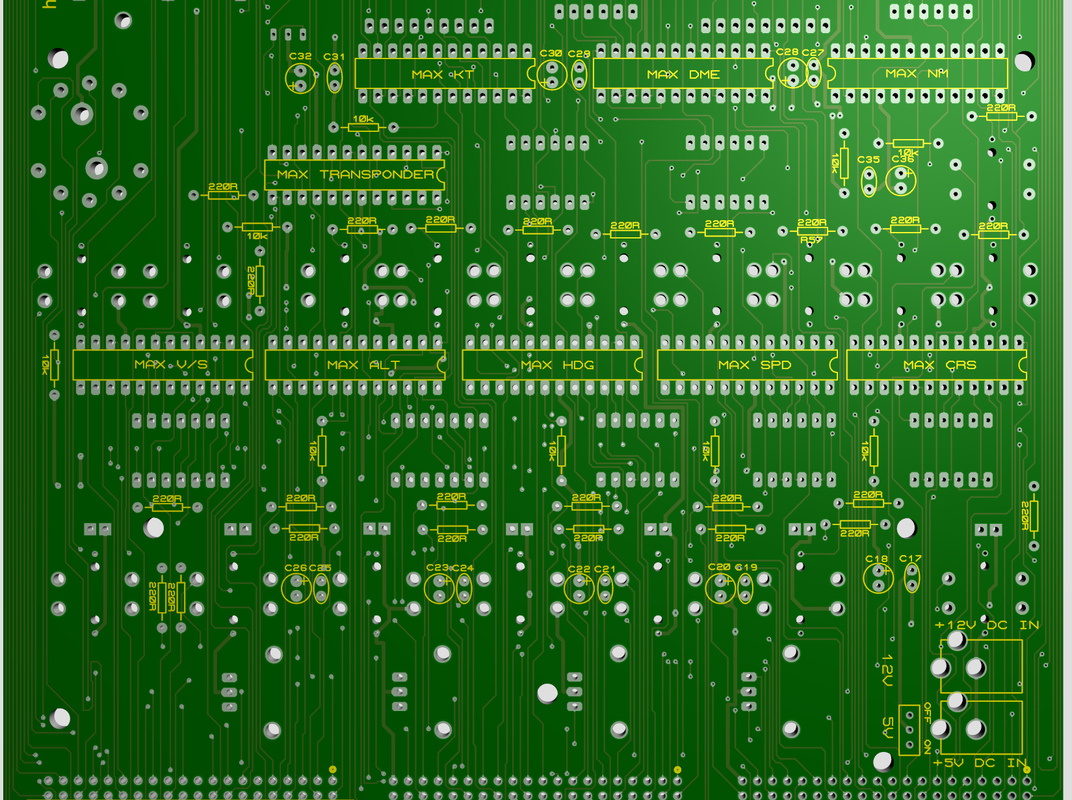
|
In the picture below you will see the pinouts looking from the back of the board

|
The excel file will help you to program the radio with mobiflight. For example:
Com1AudioSwitch is connected to Arduino number 3 on pin 22 and so on ... O LED is connected to Arduino number 1 on pin 31 ... DIN1 is connected to Arduino number 1 on pin 22 ... 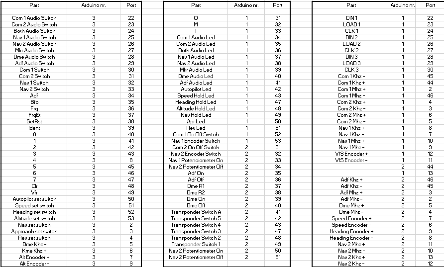
|
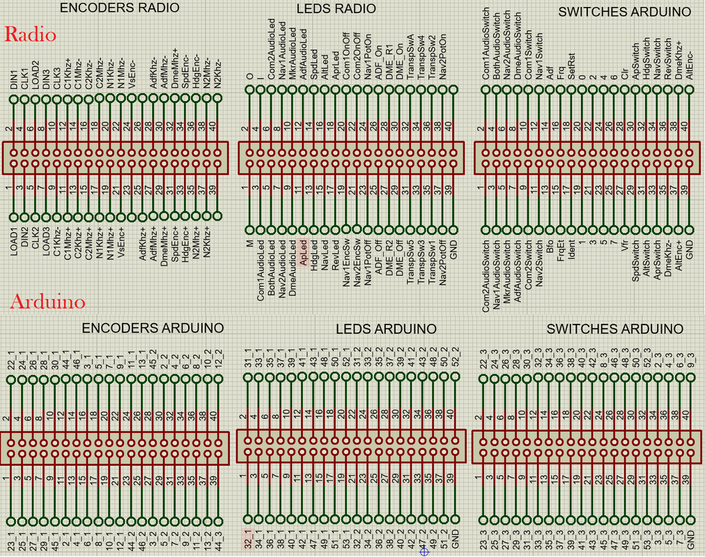
|
Arduino Pinouts
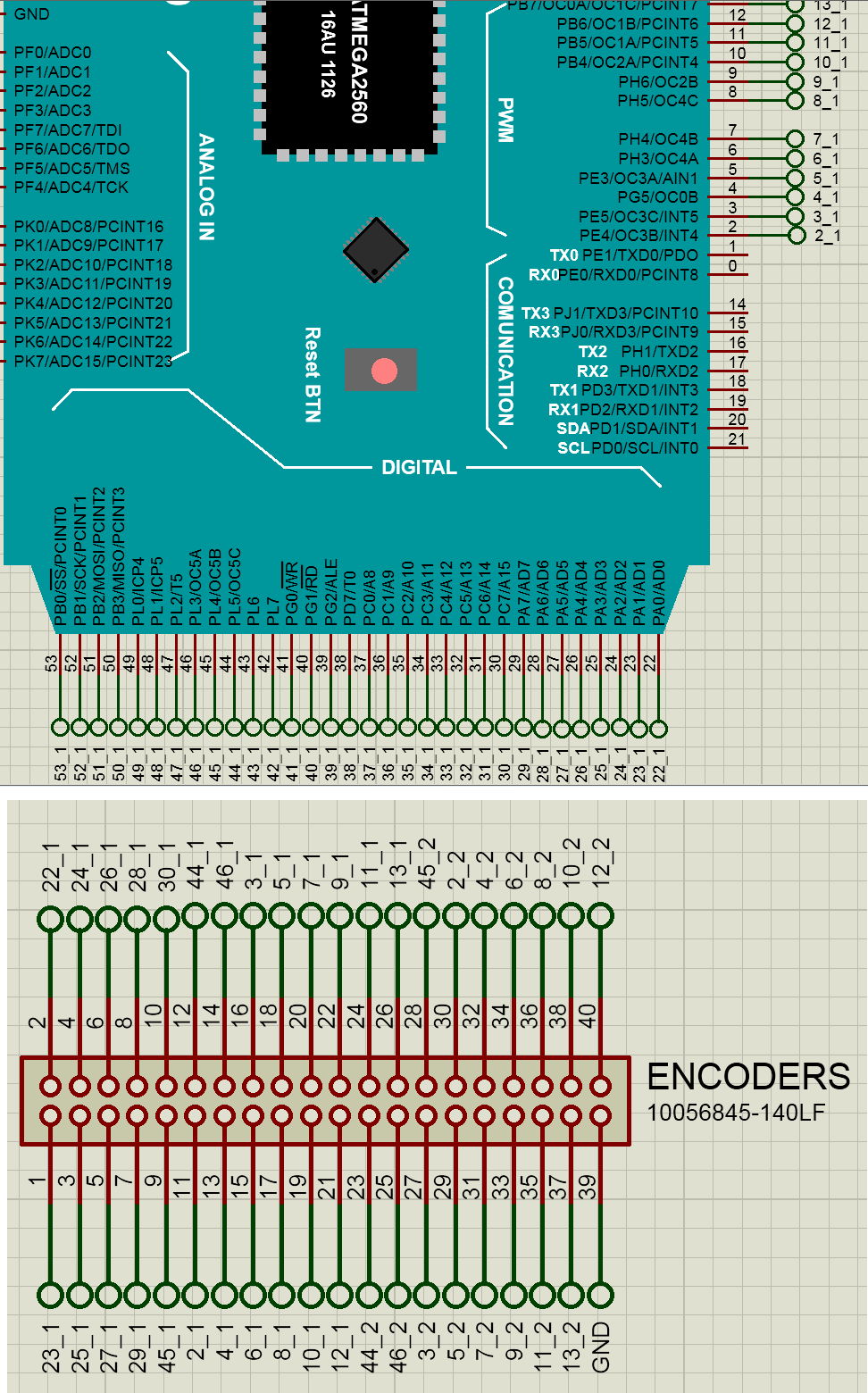
|
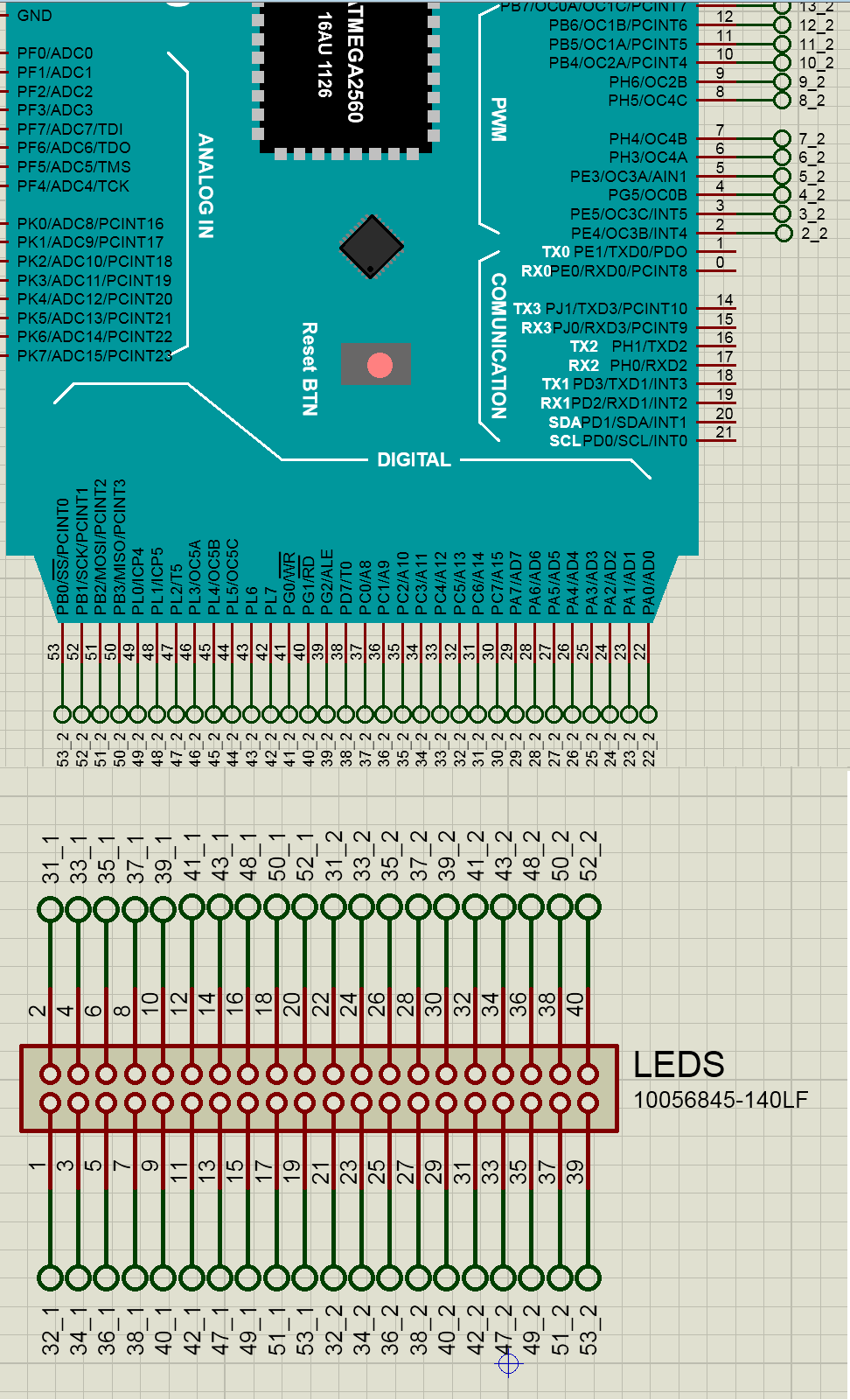
|
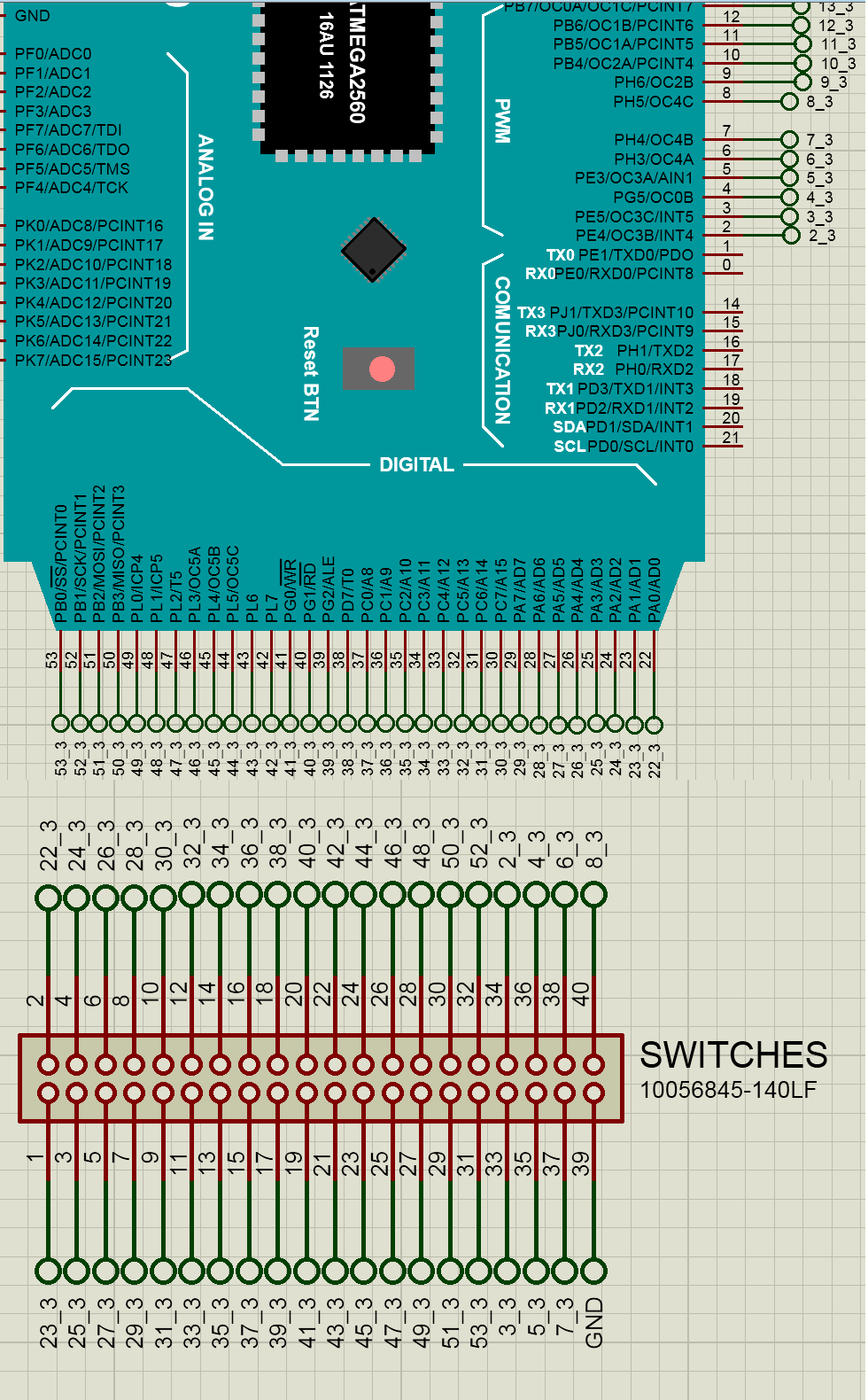
|
Arduino Extra Pinouts
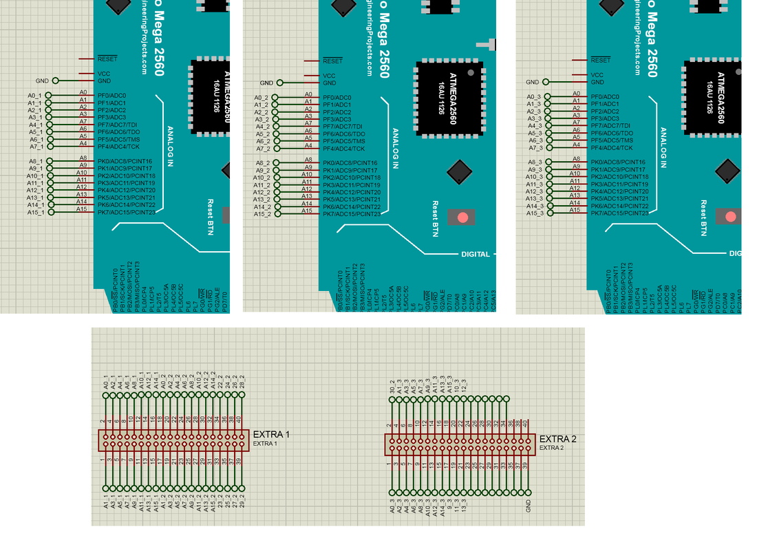
Radio stack V1.1
A little update: I've been working on creating Radio PCB's and GPS PCB which would be better and cleaner even though I don't have enough time.
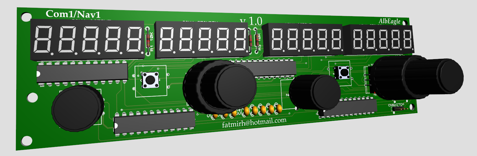
I have chosen to go with the whole board version, it will be less wires and easier to be mounted.
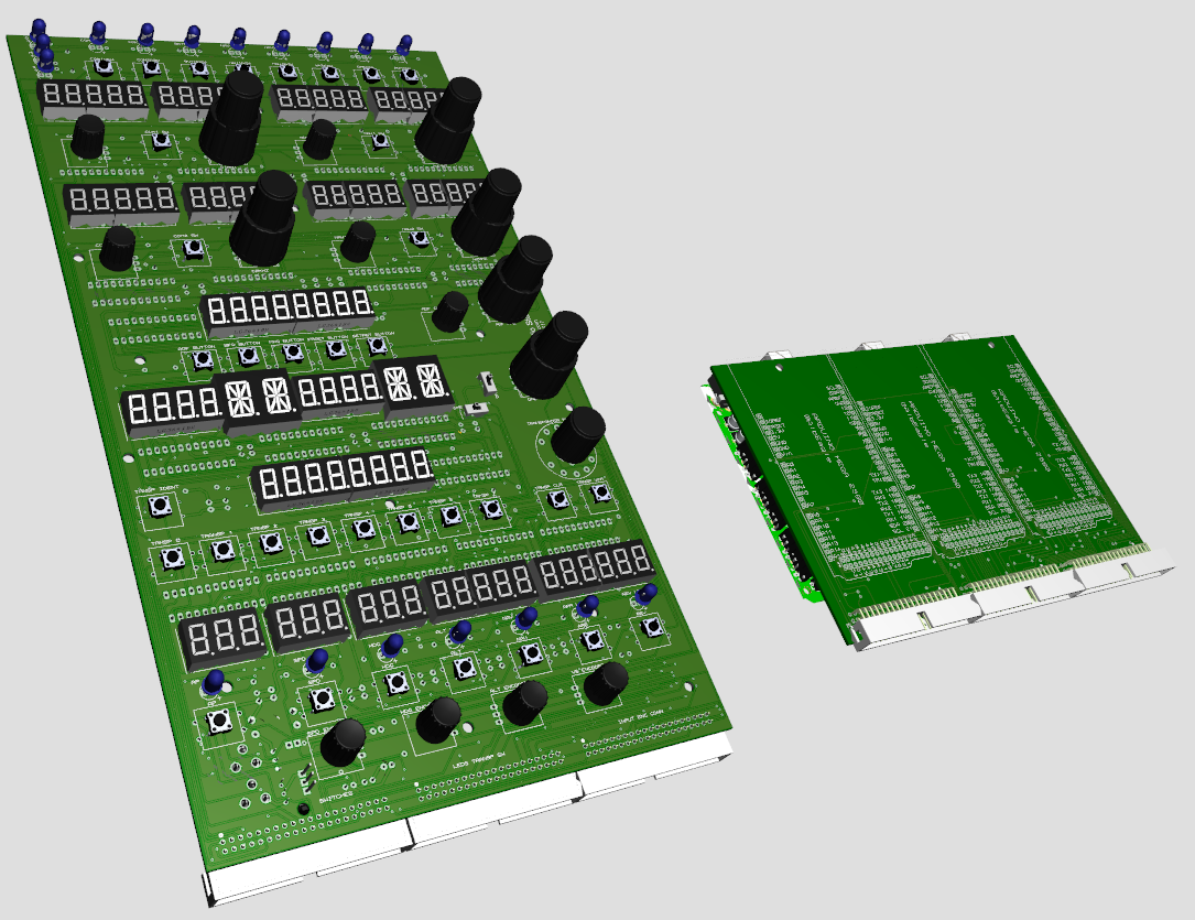
Arduino shield will be mounted on the back ov the radio with spacers and will be connected with 3 x 40 pin flat ribbon cable. Max7219 chips and 7 segment displays will be replaceable because on the pcb I will be soldering IC sockets for both displays and max chips.
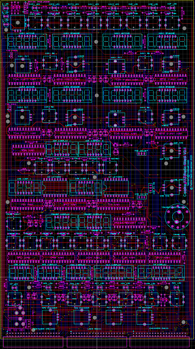
Here you can see the PCB layout.
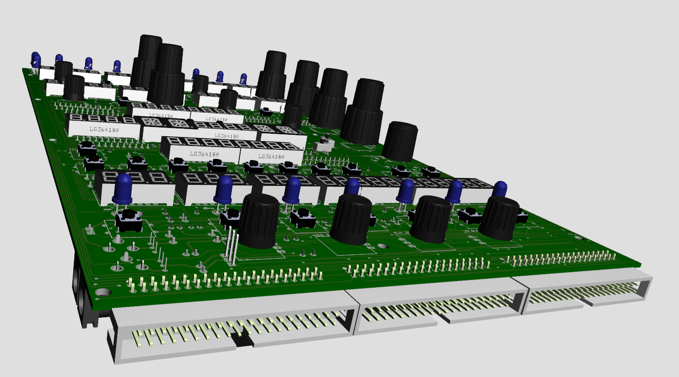
There are going to be 3x40 outputs from the Radio to be connected to the Arduino shield.
|
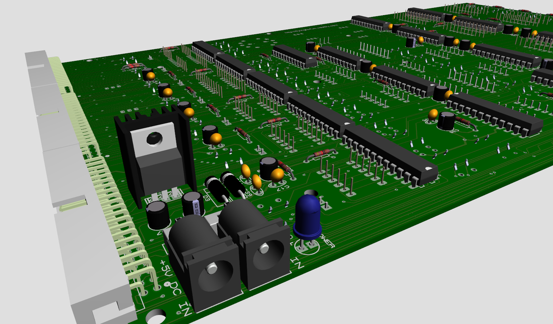
I have added the possibility to use either +12V or 5V DC Input.
|
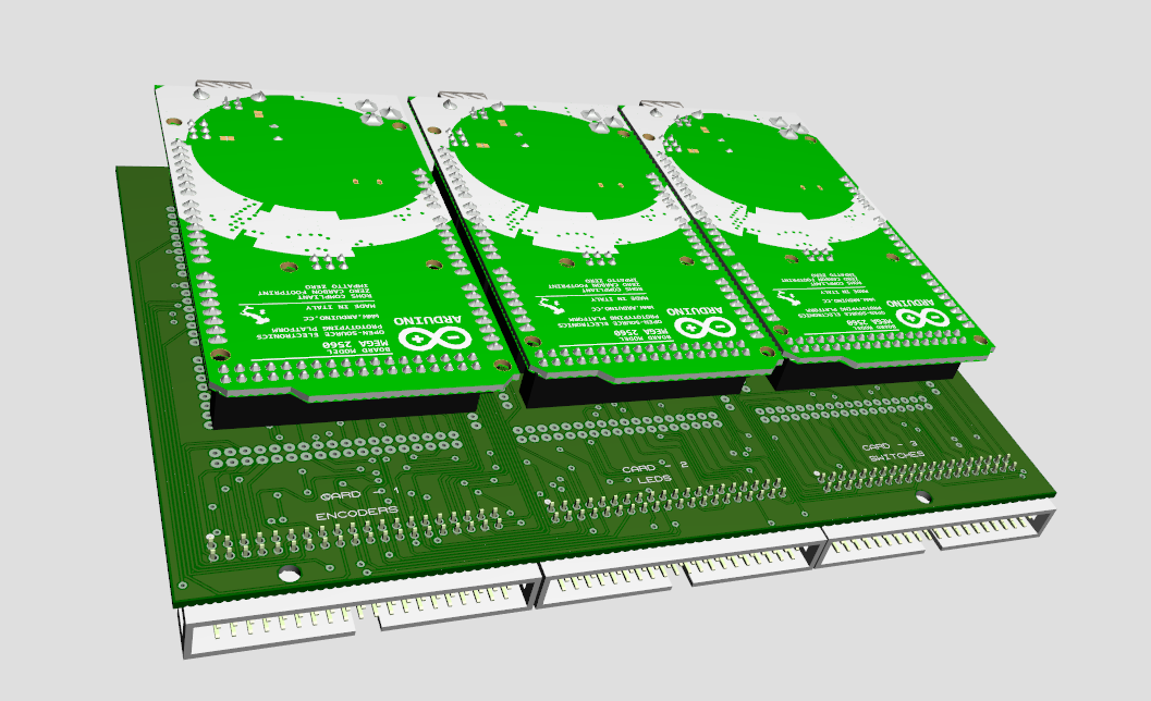
There are 3xArduino Mega2560 boards needed for the radio to be fully funtional.
|
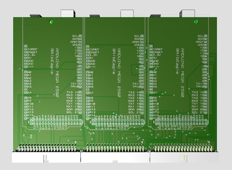
Arduino shield will be mounted on the back of the radio with pcb spacers and will be connected to the radio through 3x40 pin flat ribon cables.
|
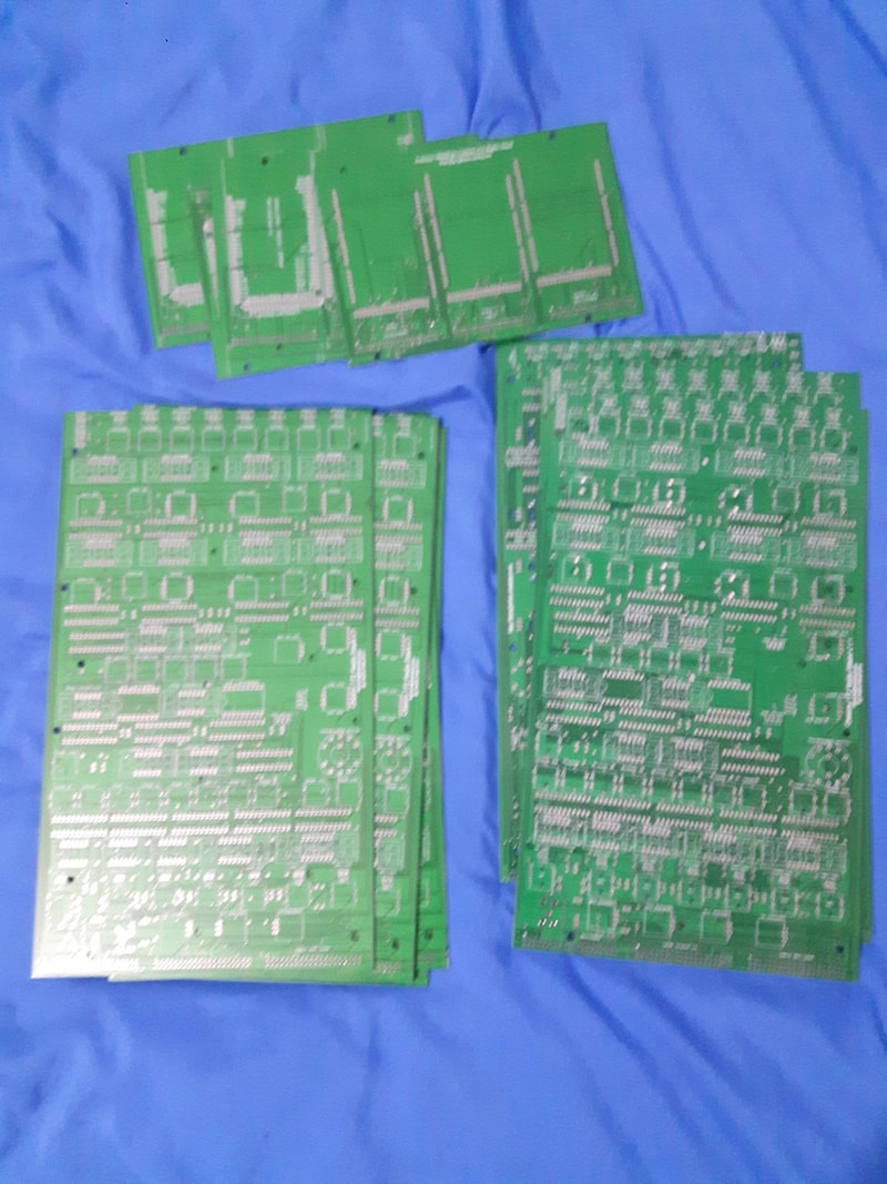
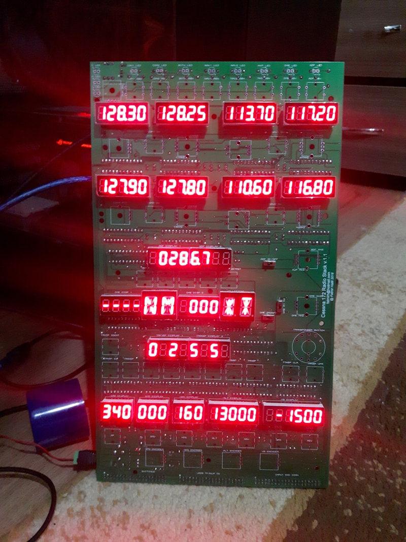
Update 04.03.2018 The PCB's arrived and I started to install the components.
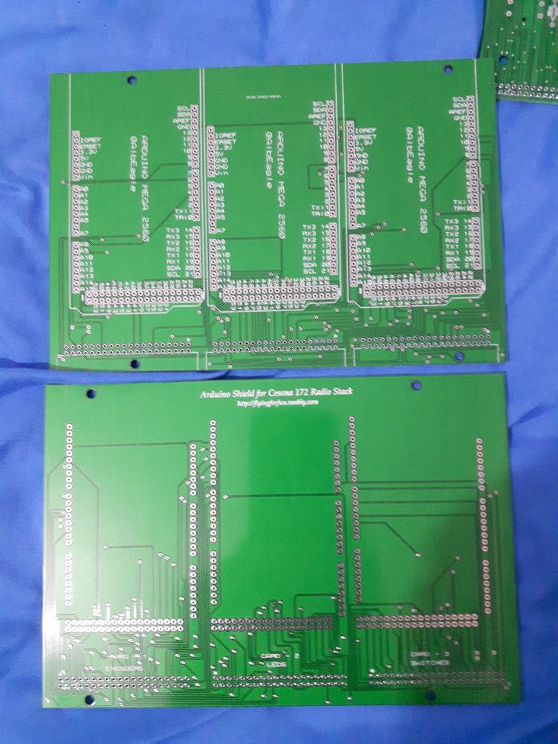
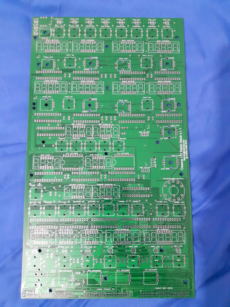
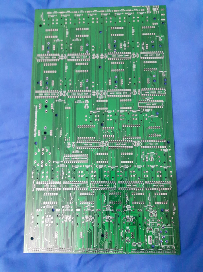
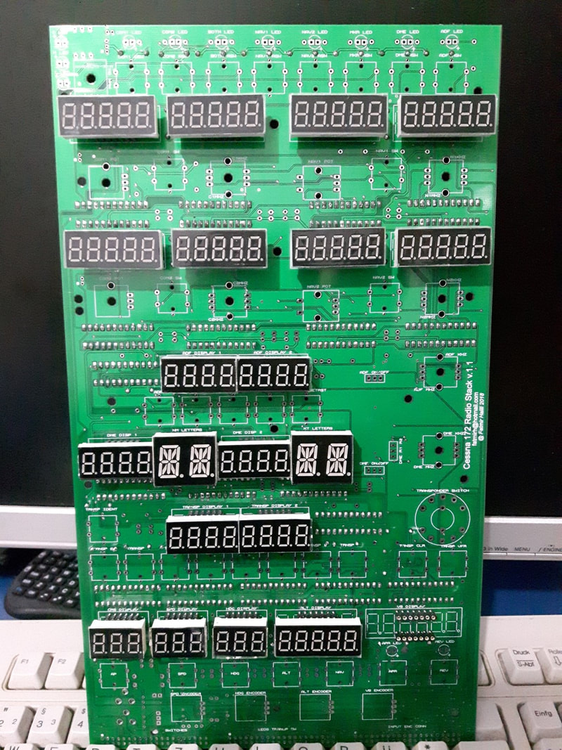
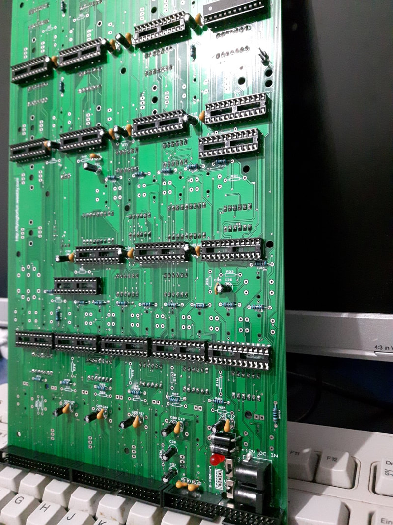
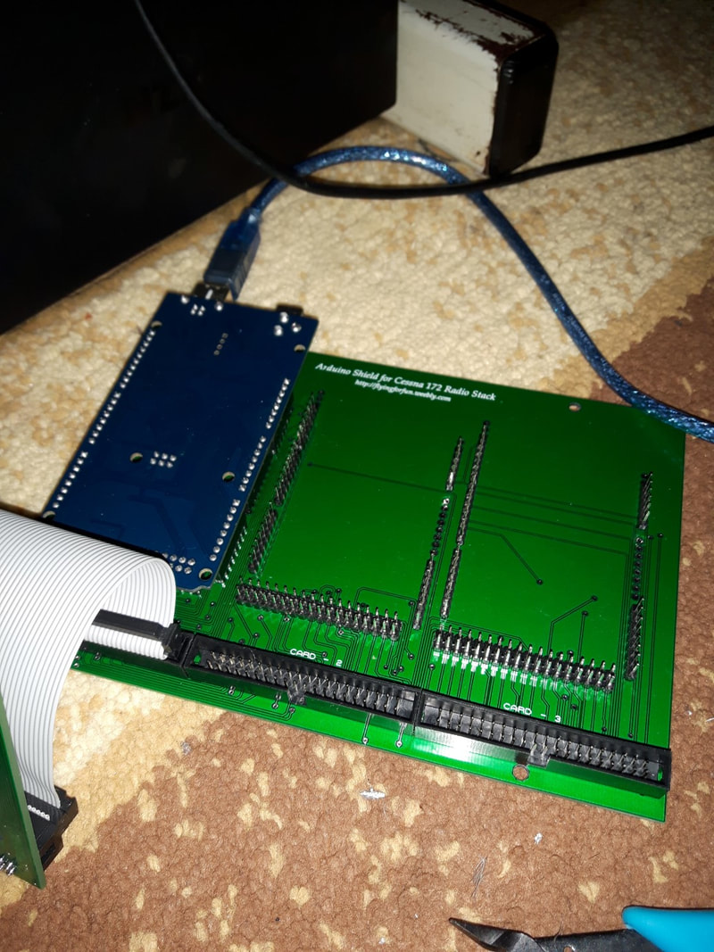
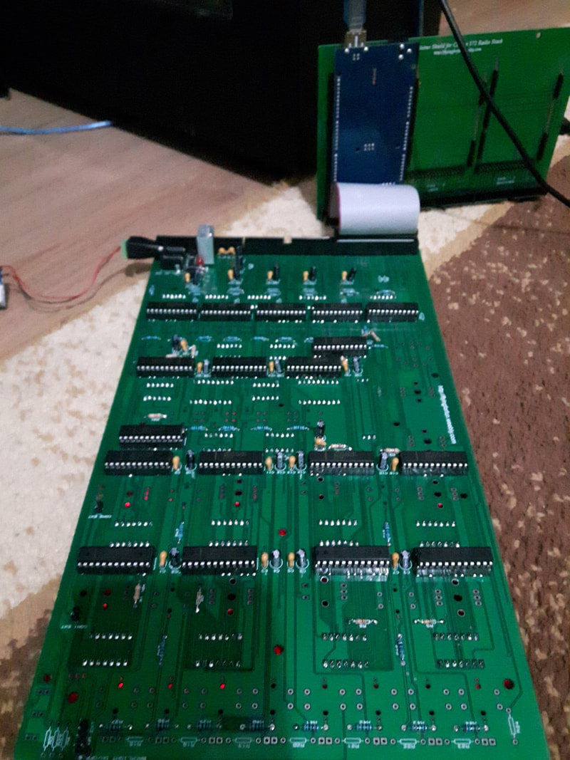
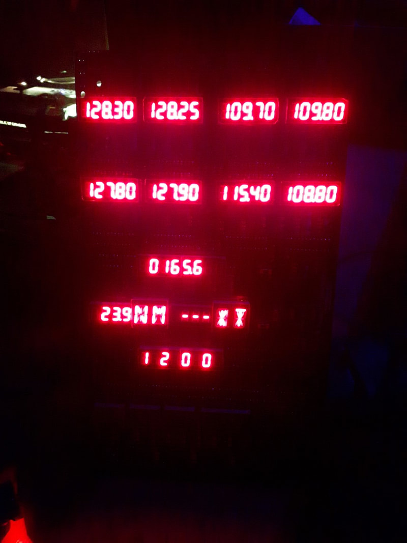
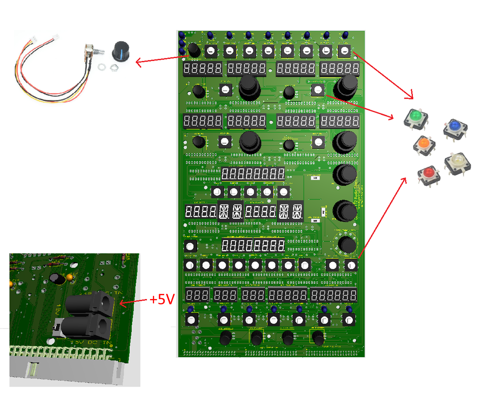
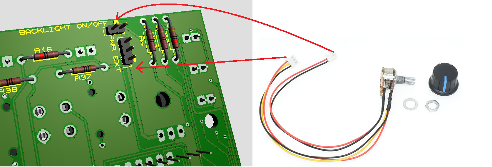
Backlight Option
The radio is designed to also use buttons with leds for backlight buttons. With the switch you can turn on/off the lights and dim them as you wish. The problem with these switches are the knobs which are hard to attach, so you have to come up with a way (maybe 3D Print them). You have to take that in consideration if you choose to go with this option.
|
|
Radio Components
Update 29.05.2023
Below an excel file with the components and links (no affiliate links).
Below an excel file with the components and links (no affiliate links).
Update 29.05.2023
Below an excel file with the components and links (no affiliate links).
Below an excel file with the components and links (no affiliate links).
| BOM with links updated 29.05.2023 |
(I'm not part of any affiliate program, the links below and in the entire website are the cheapest I could find on the web. You should always search for new prices)
Since the most expensive part of the radio stack and the GPS are the dual concentric encoders, my intentions were to make it cheap, so you need two encoders EC12 plastic encoders (EC12 link here) to mount on both sides of the PCB based on this principle:
Dual concentric encoders.
If you don't have a 5V power supply, you can use this step down converter
24V/12V to 5V 5A converter
It is also designed to have tactile buttons with led's built in it like these ones:
Tactile buttons with leds.
A problem about the led tactile buttons is that it is hard to install the knob if you look at one of them. That's why this is optional as these normal tactile buttons have the same dimensions and were meant for it in the first place.
Normal Tactile buttons
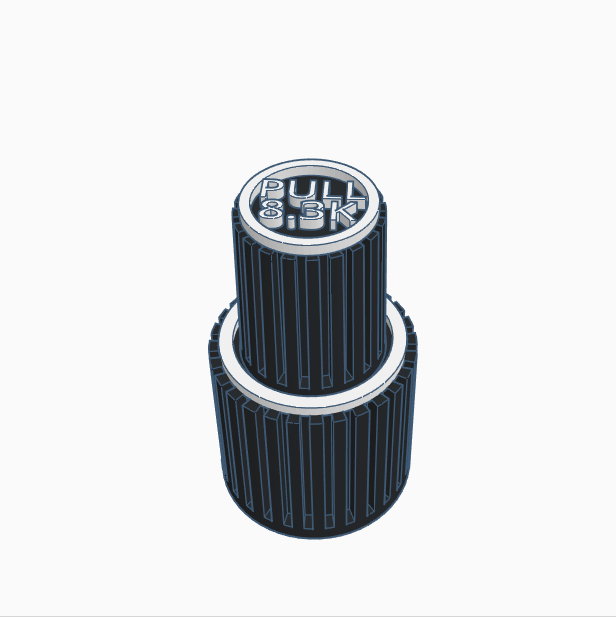
Knobs need to be 3D Printed ( you can download them HERE ) or if you don't have a 3D Printer you can use these ones for the bigger knobs
Big Knobs
and these for the smaller ones
Small nobs
As connector you can use this headers:
Headers
And the cables here:
Cable
For PWR ON/Off encoder I wanted to use this one with a different knob:
On/Off Encoder
And the V1 Enc is a normal Encoder.
If you use the buttons with leds, you need Resistors on the back (size needs to be calculated from you depending what tactile buttons you are going to use).
7 segment displays:
3 digit 7 segment display 0.36inch CC RED
4 digit 7 segment display 0.36inch CC RED
6 digit 7 segment display 0.36inch CC RED
10 x 5 digit 7 segment display 0.36inch CC RED
If you don't want to solder the displays directly on the PCB than you can use these sockets in case any of the displays won't work you can change them
Round Sockets
You need 18x Max7219 Chips
20 x Max7219
If you don't want to solder Max7219 chips directly to the board so you can change them if any one gets burned than you can use this sockets
Max7219 socket
3mm Led mount
5mm Led mount
330 Ohm resistors
10K resistors
3Pin 2 Position Switches
25V 10uF Capacitors
50V 0.1uF Capacitors
2.1mm DC Power suply Jack
You also need 2x 2 digit 14 segment displays for NM and KT letters. Just search on ebay, amazon, aliexpress or elsewhere for them but you need to be careful and purchase Common Cathode. Common Anode doesn't work with Max7219 chips.
Since the most expensive part of the radio stack and the GPS are the dual concentric encoders, my intentions were to make it cheap, so you need two encoders EC12 plastic encoders (EC12 link here) to mount on both sides of the PCB based on this principle:
Dual concentric encoders.
If you don't have a 5V power supply, you can use this step down converter
24V/12V to 5V 5A converter
It is also designed to have tactile buttons with led's built in it like these ones:
Tactile buttons with leds.
A problem about the led tactile buttons is that it is hard to install the knob if you look at one of them. That's why this is optional as these normal tactile buttons have the same dimensions and were meant for it in the first place.
Normal Tactile buttons
Knobs need to be 3D Printed ( you can download them HERE ) or if you don't have a 3D Printer you can use these ones for the bigger knobs
Big Knobs
and these for the smaller ones
Small nobs
As connector you can use this headers:
Headers
And the cables here:
Cable
For PWR ON/Off encoder I wanted to use this one with a different knob:
On/Off Encoder
And the V1 Enc is a normal Encoder.
If you use the buttons with leds, you need Resistors on the back (size needs to be calculated from you depending what tactile buttons you are going to use).
7 segment displays:
3 digit 7 segment display 0.36inch CC RED
4 digit 7 segment display 0.36inch CC RED
6 digit 7 segment display 0.36inch CC RED
10 x 5 digit 7 segment display 0.36inch CC RED
If you don't want to solder the displays directly on the PCB than you can use these sockets in case any of the displays won't work you can change them
Round Sockets
You need 18x Max7219 Chips
20 x Max7219
If you don't want to solder Max7219 chips directly to the board so you can change them if any one gets burned than you can use this sockets
Max7219 socket
3mm Led mount
5mm Led mount
330 Ohm resistors
10K resistors
3Pin 2 Position Switches
25V 10uF Capacitors
50V 0.1uF Capacitors
2.1mm DC Power suply Jack
You also need 2x 2 digit 14 segment displays for NM and KT letters. Just search on ebay, amazon, aliexpress or elsewhere for them but you need to be careful and purchase Common Cathode. Common Anode doesn't work with Max7219 chips.
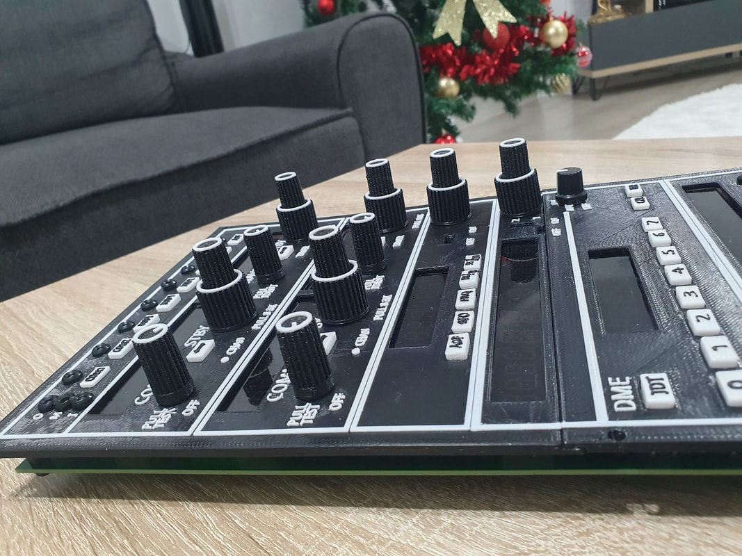
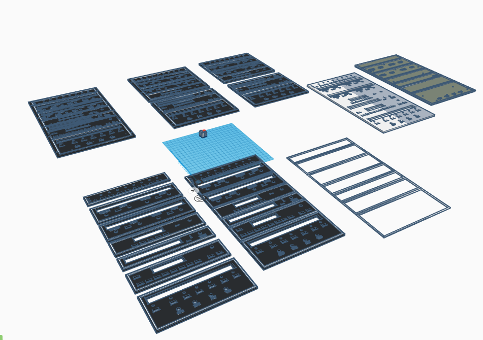
Faceplate, knobs and buttons
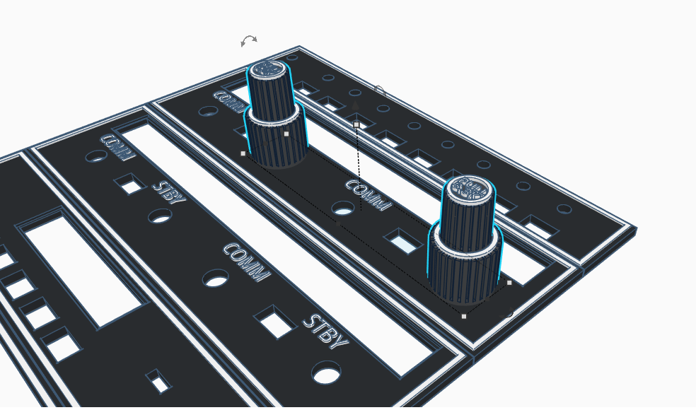
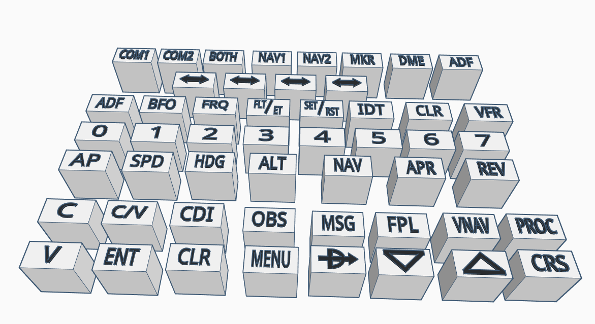
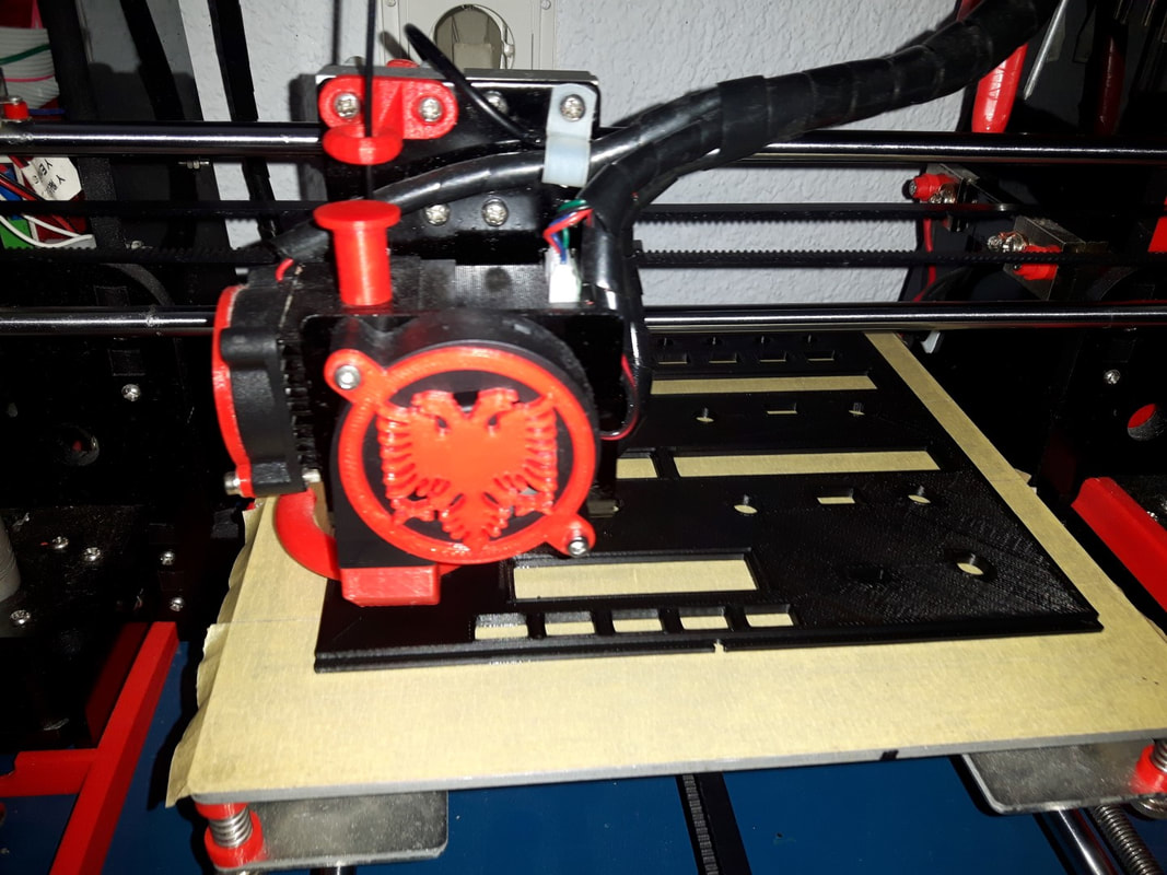
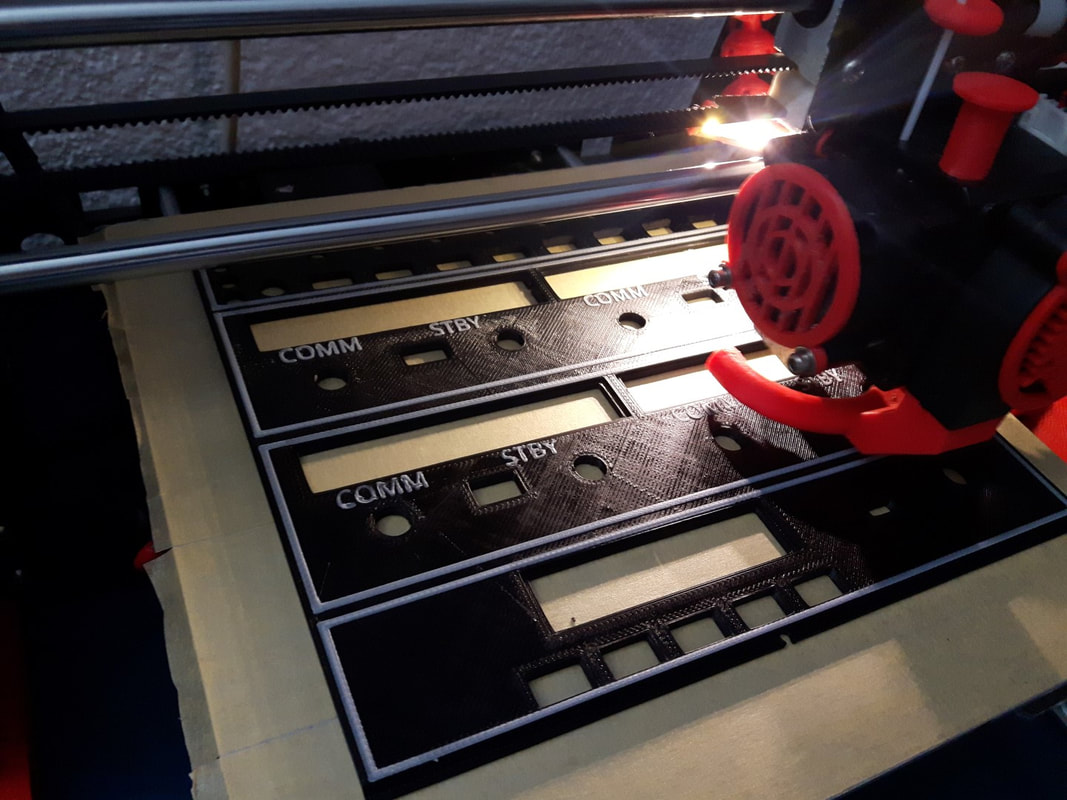
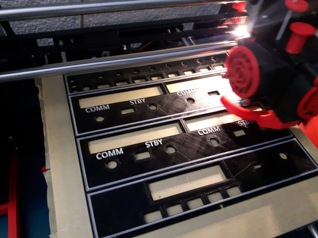
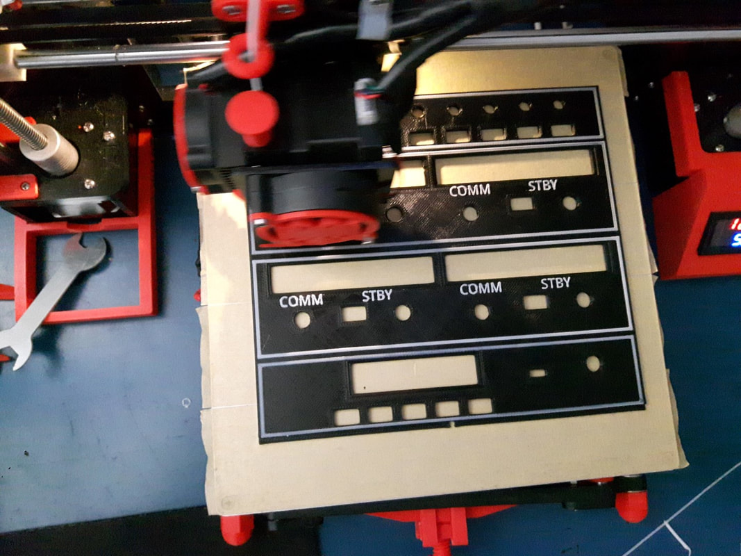
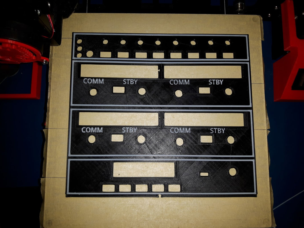
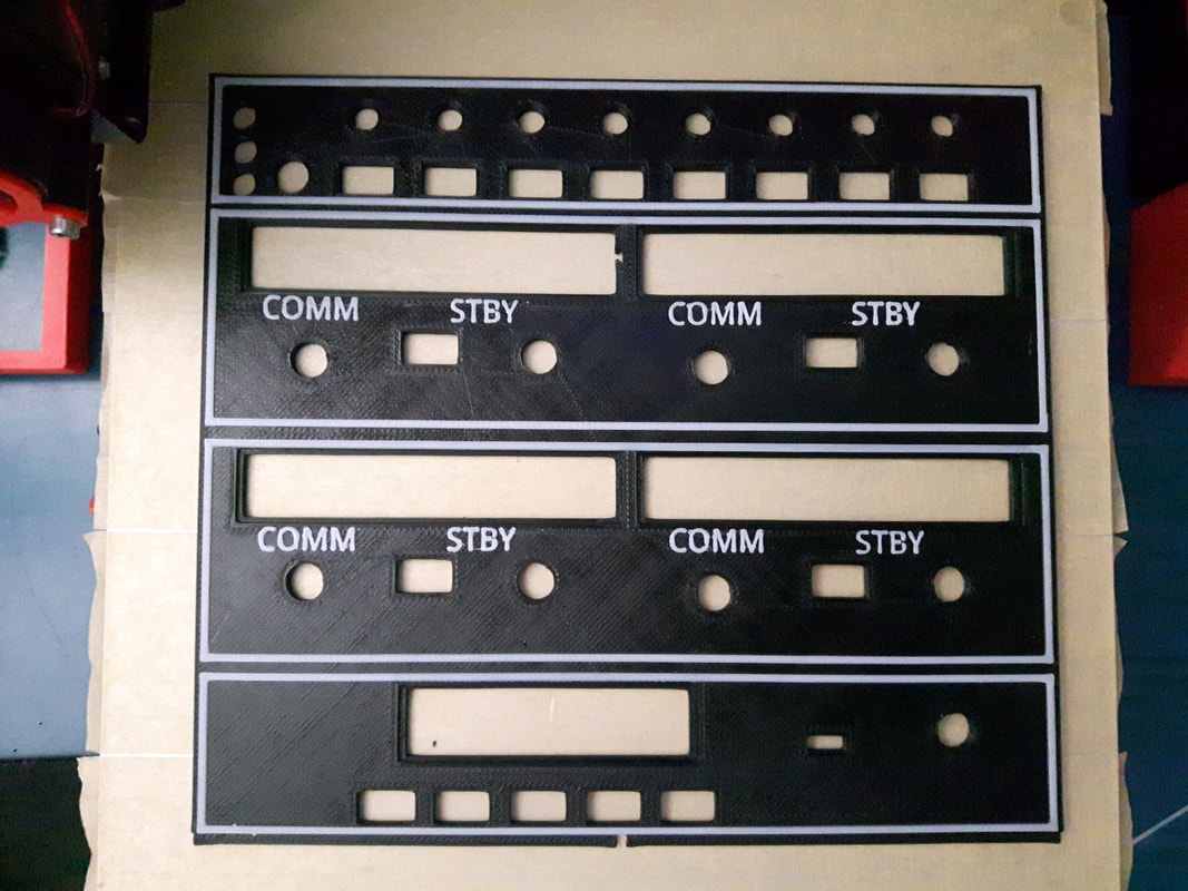
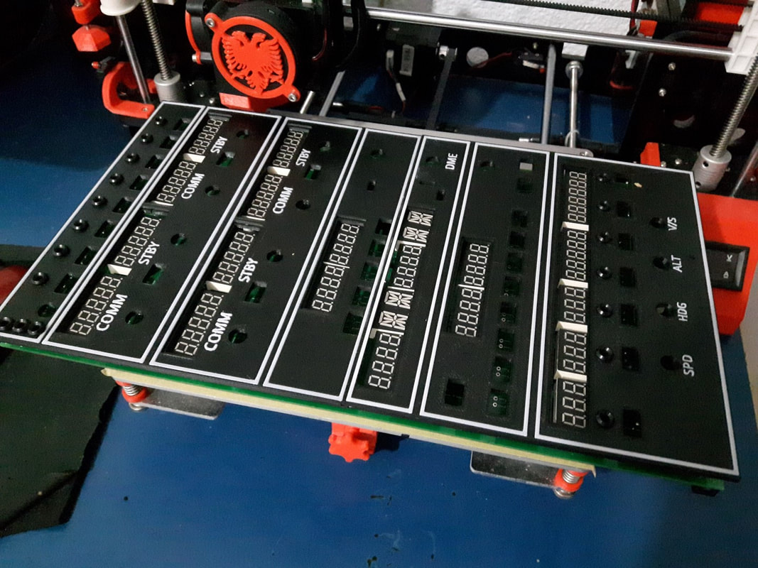
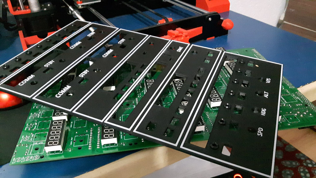
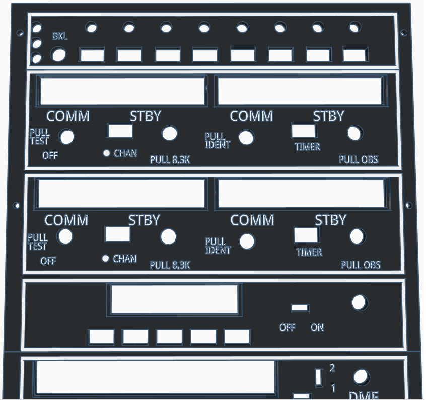
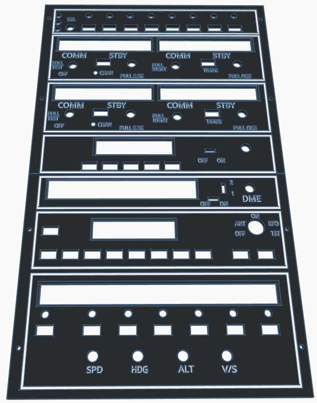
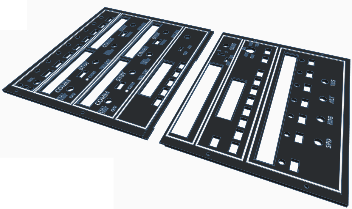
Update: 27.03.2018 Working on the face plate of the Radiostack. It will be 3D printable, in separate pieces. I have also been working on the knobs and buttons. This face plate fits only on the PCB version of the radio and CAN NOT be used with the DIY version of the radio because it is different and has different dimensions. I'm still working on it so changes may apply.
|
|
|
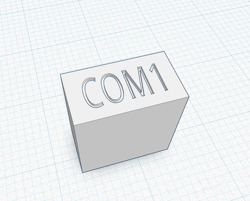
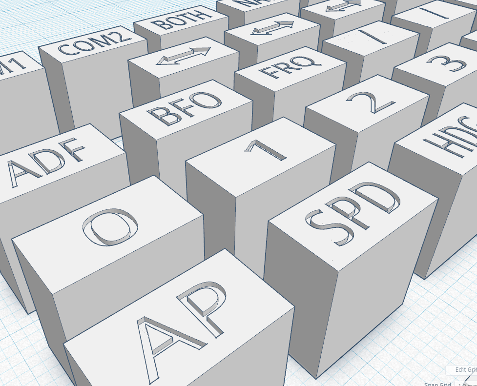
Another possible way would to print the letters engraved to the buttons and fill them with white color. I never tried this method, so you could see if it will probably give better results. I will links you have only one button (Com1) to try it out, if it turns good than you can print them all.
|
|
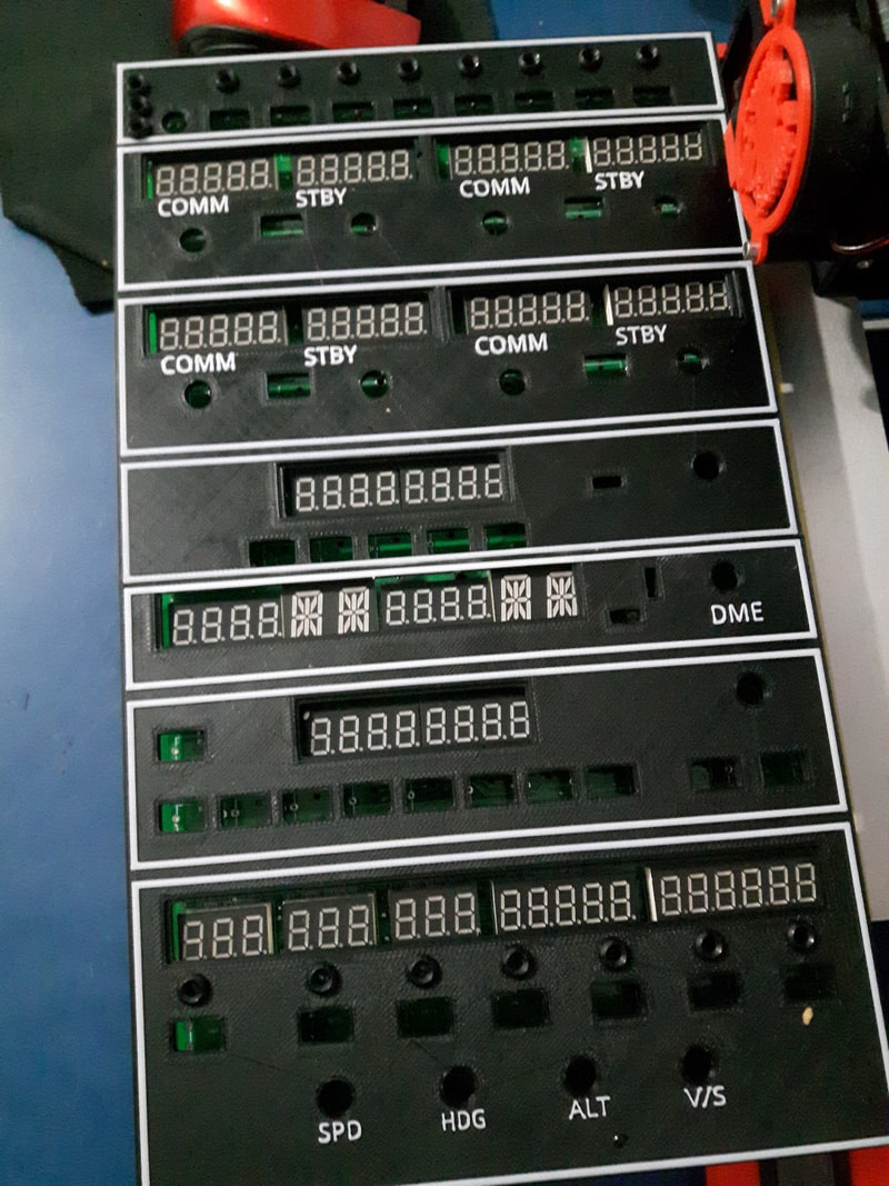
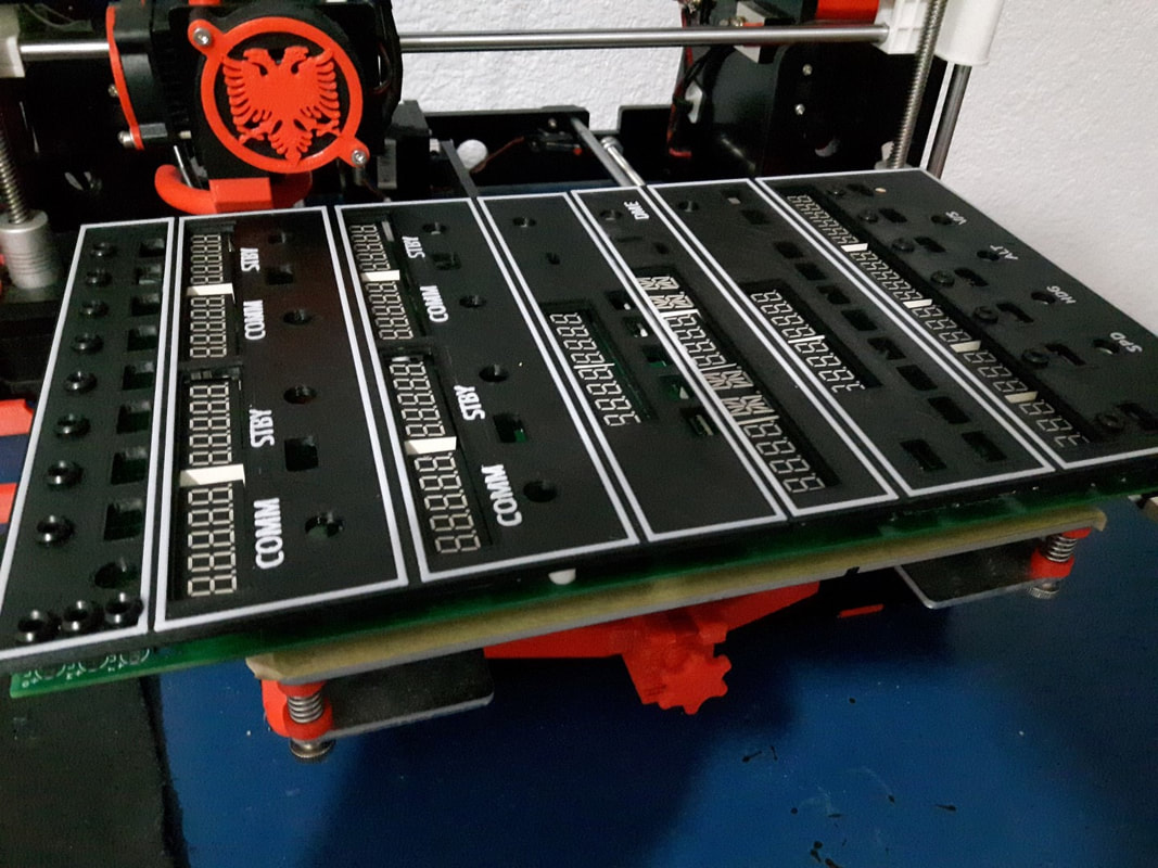
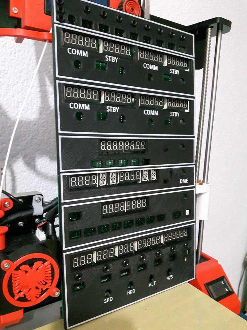
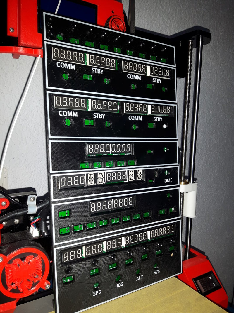
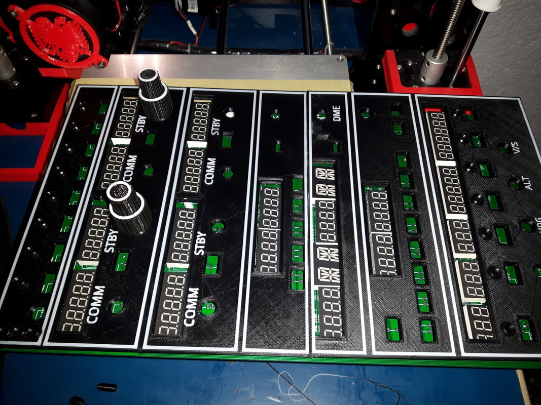
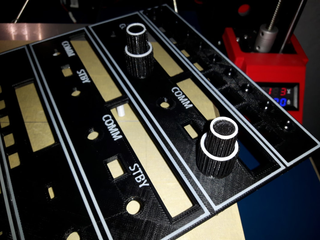
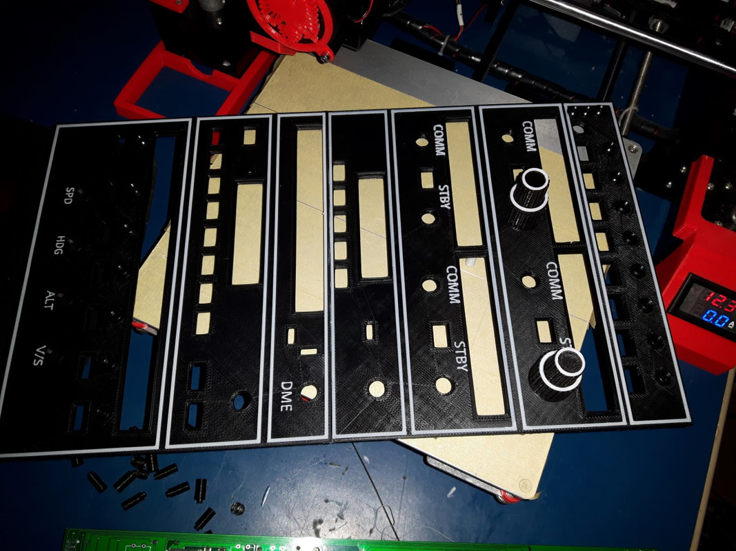
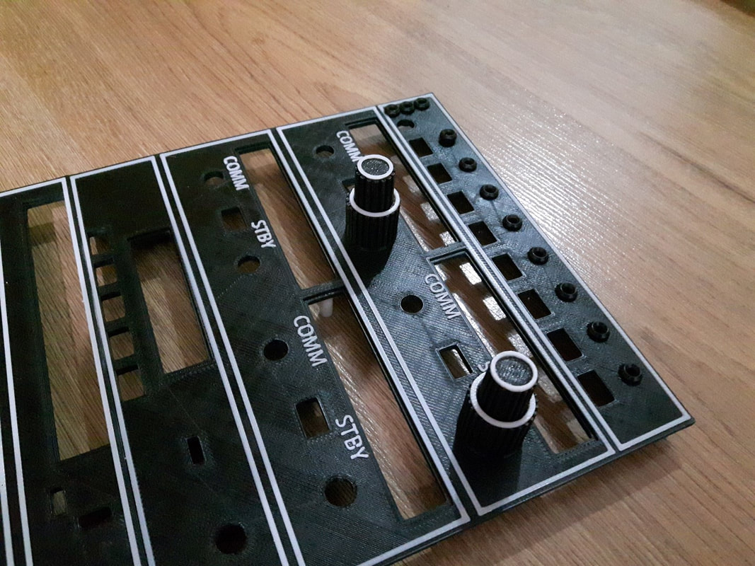
|
|
|
If you wish to modify the faceplate, in the download section you can request the link for the tinkercad file. Feel free to modify it as you need.
2015, Copyright AlbEAGLE