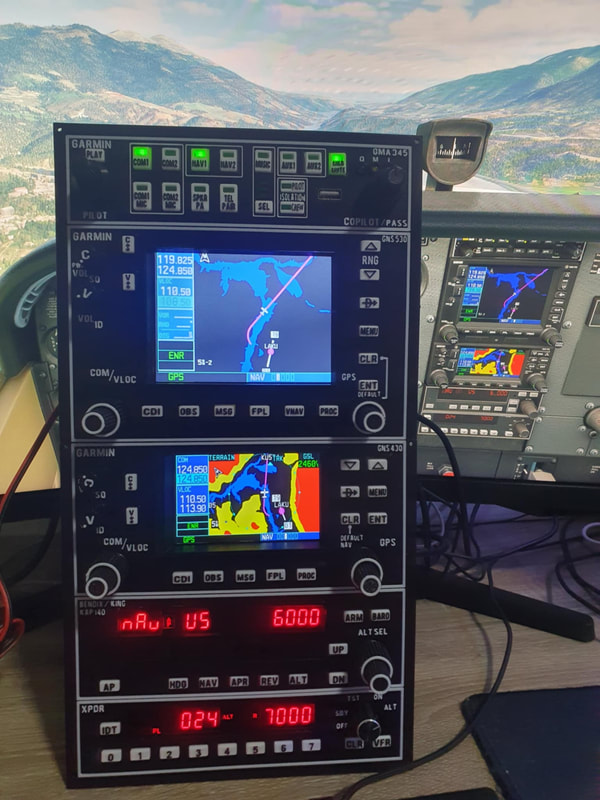
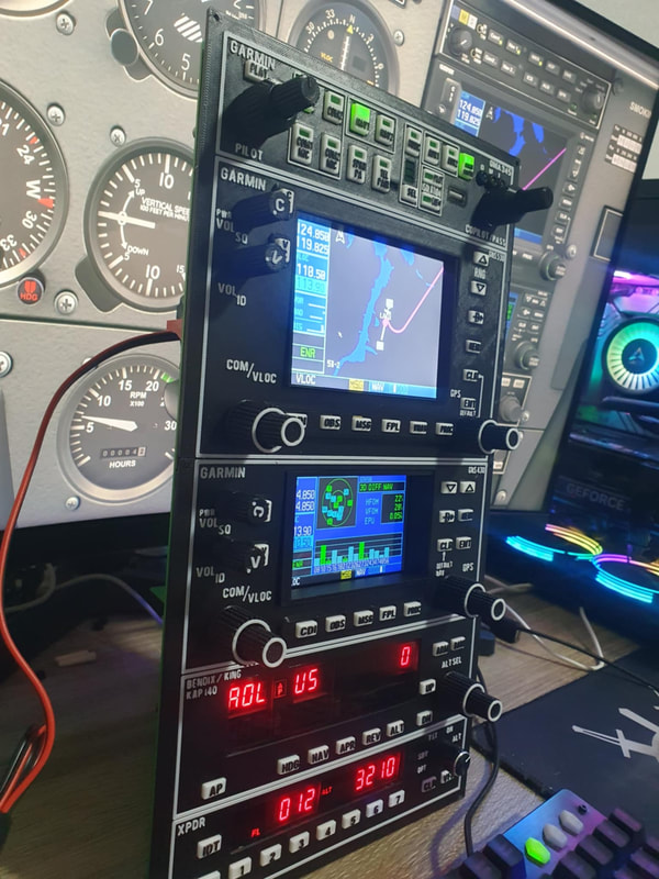
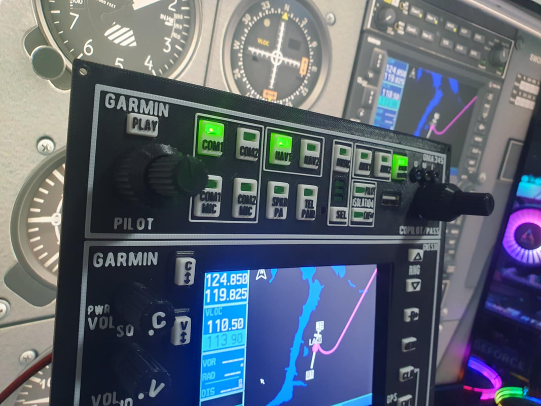
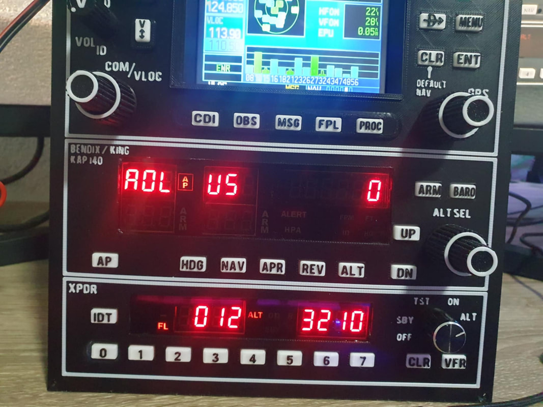
Radio with GMA 345
(work in progress...)
Content
|
|
PCB
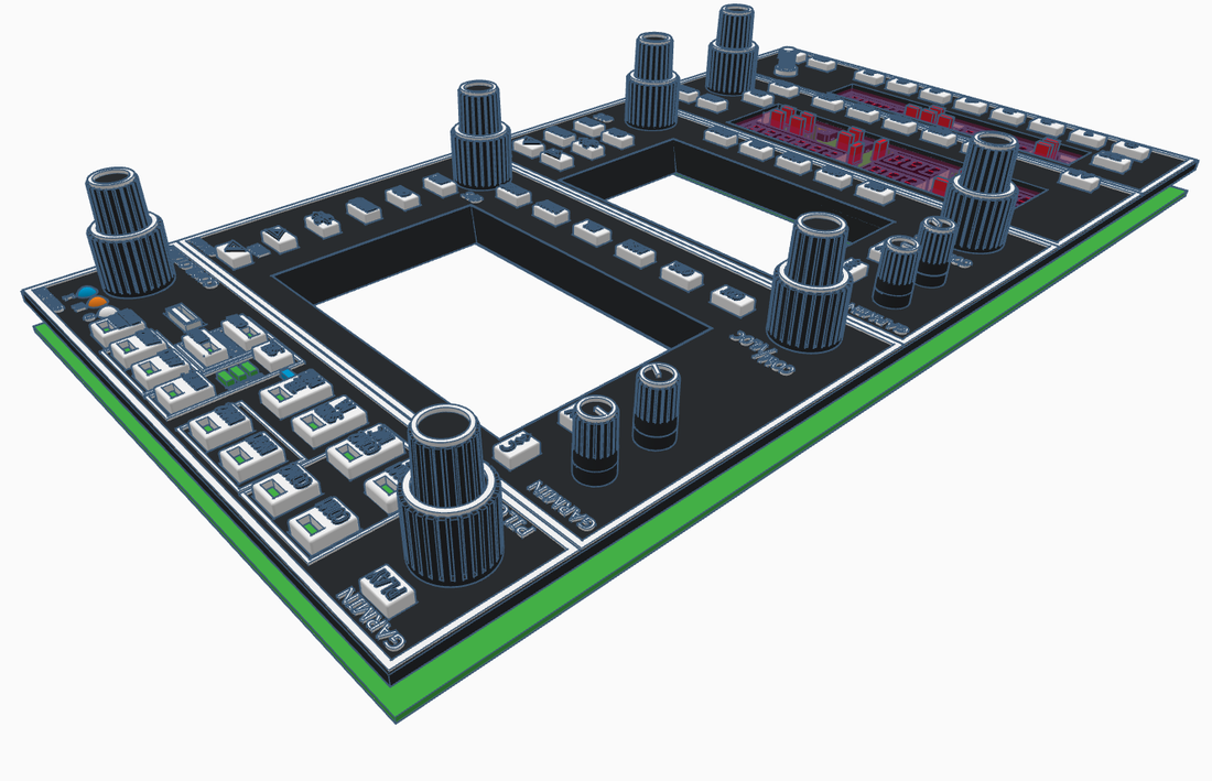
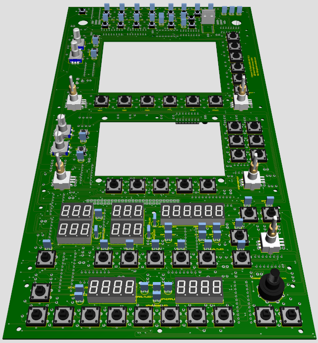
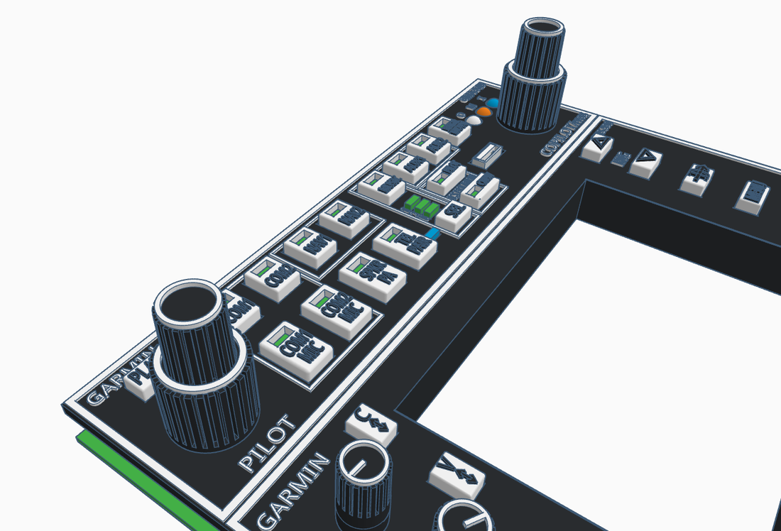
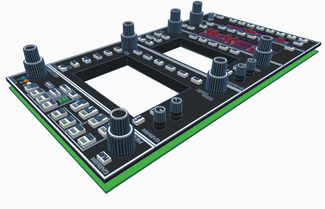
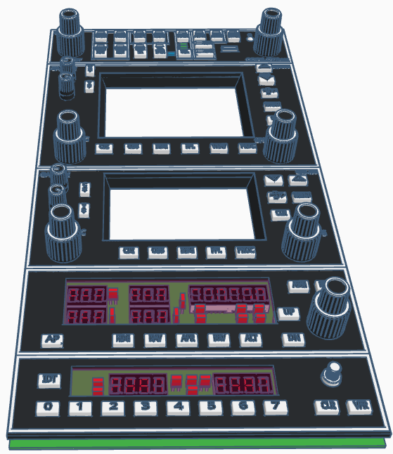
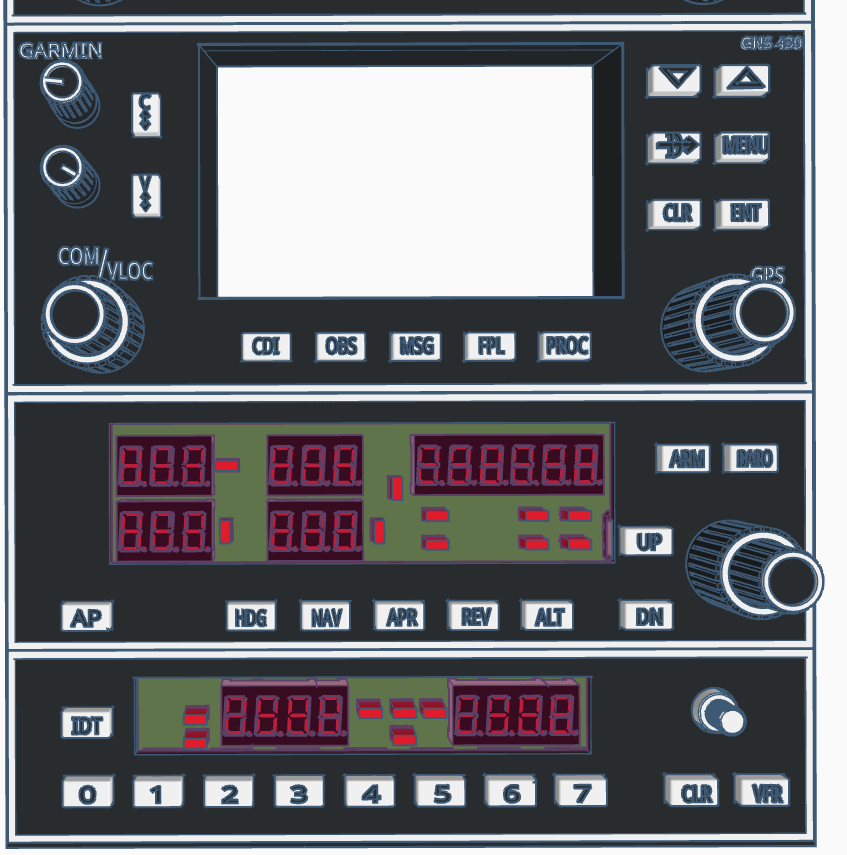
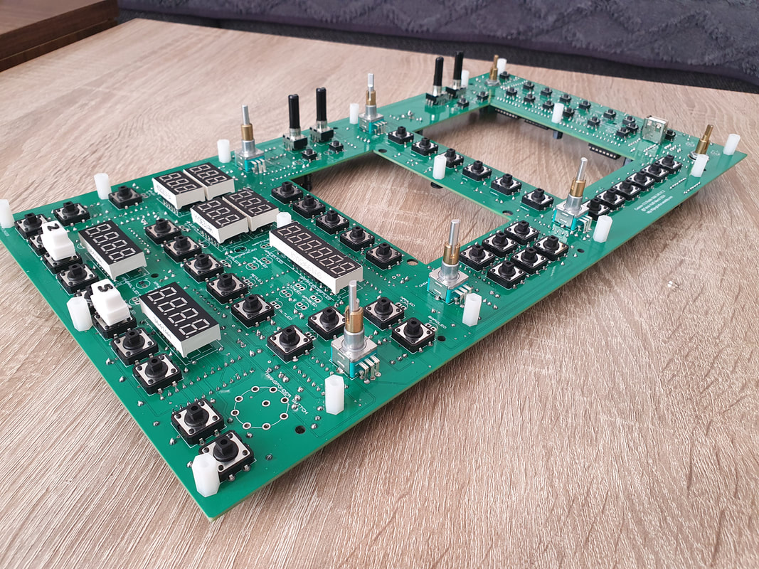
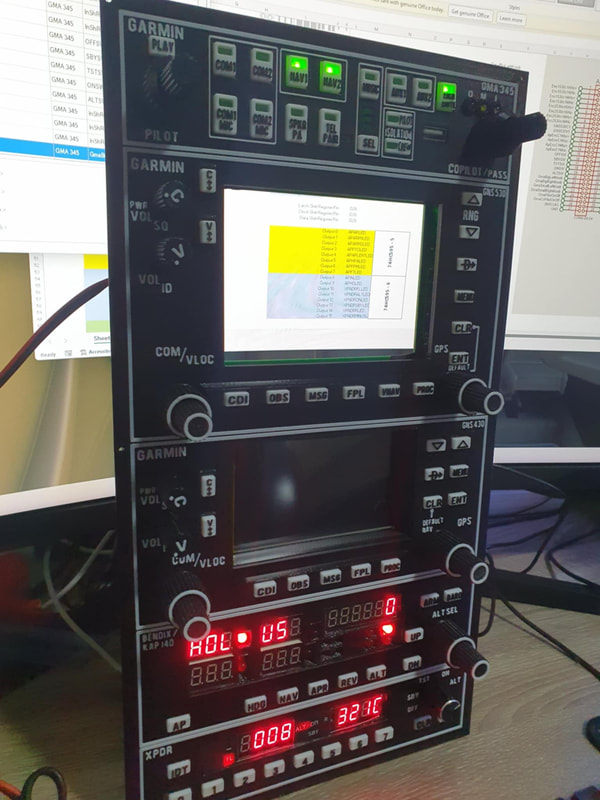
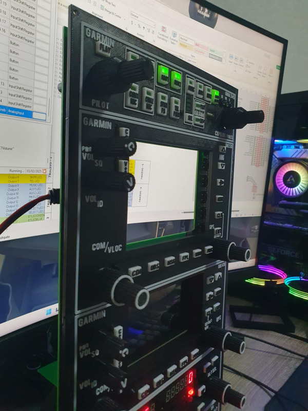
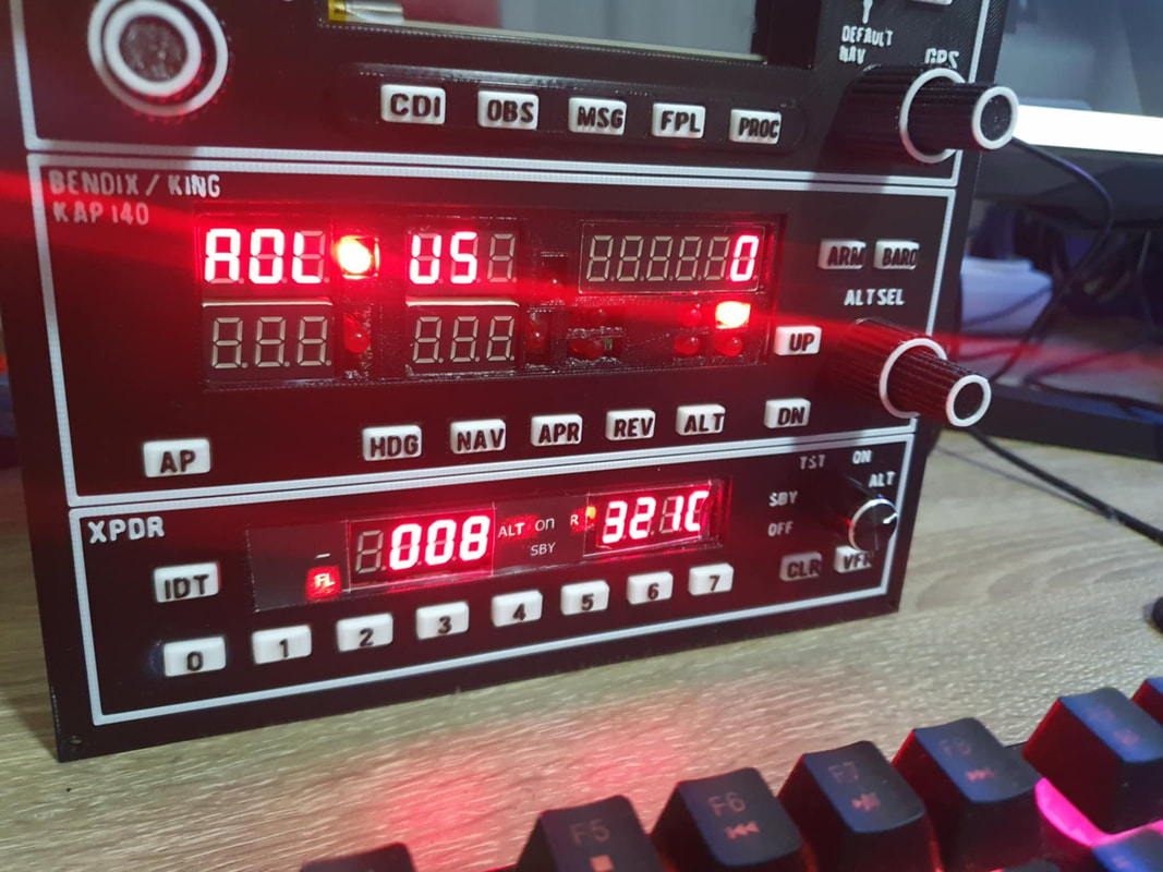
Currently working on a Cessna radio stack with GMA 345, GNS 530, GNS 430, Autopilot and XPNDR.
|
|
|
|
|
|
|
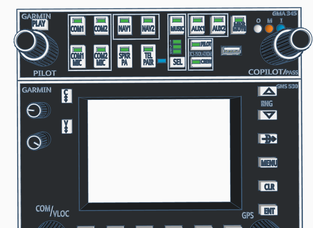
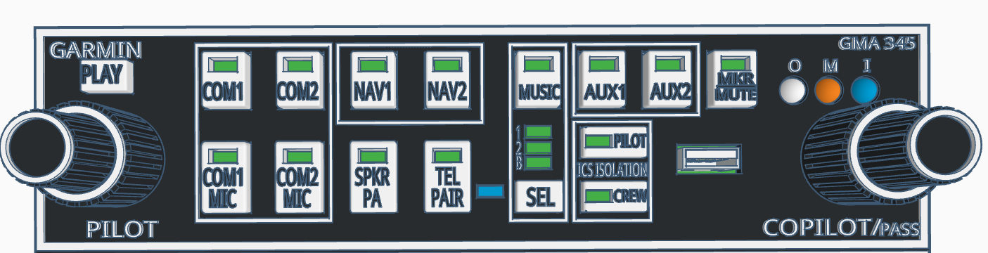
Faceplate
|
|
|
|
|
Assambly instructions
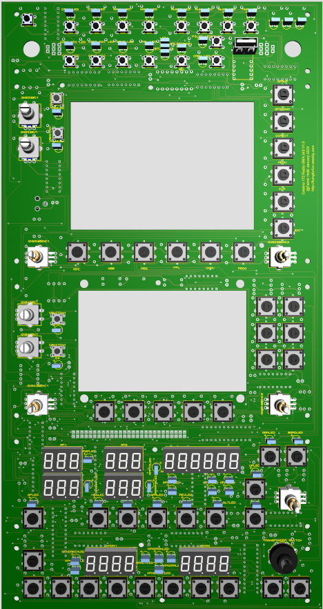
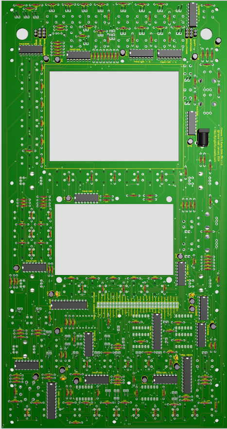
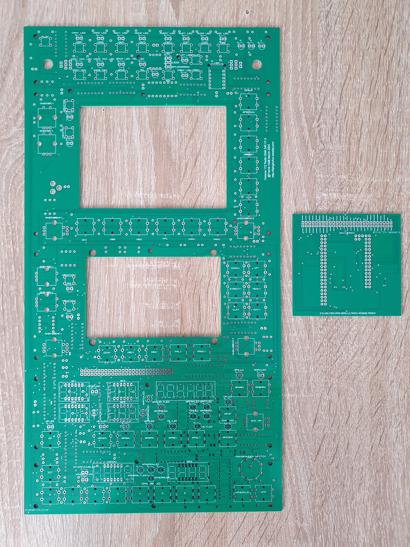
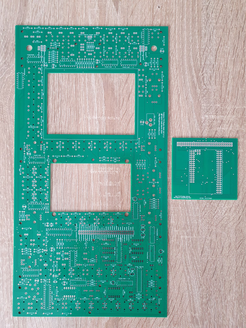
After ordering the PCB's, you will get a big one for the radio itself and a small one for the Arduino shield. This is how they look on the front and on the back:
|
Front of the PCB
|
Back of the PCB
|
Assambling the radio needs a little bit effort to solder small pins. The most important thing is to take the neccessary time and not shorten any pins, because there are really tiny pads near the pins that you need to solder. In case you are not sure, just take a magnifying glass or turn on your phone's camera and zoom in, you will be able to see those pins in places you are not certain.
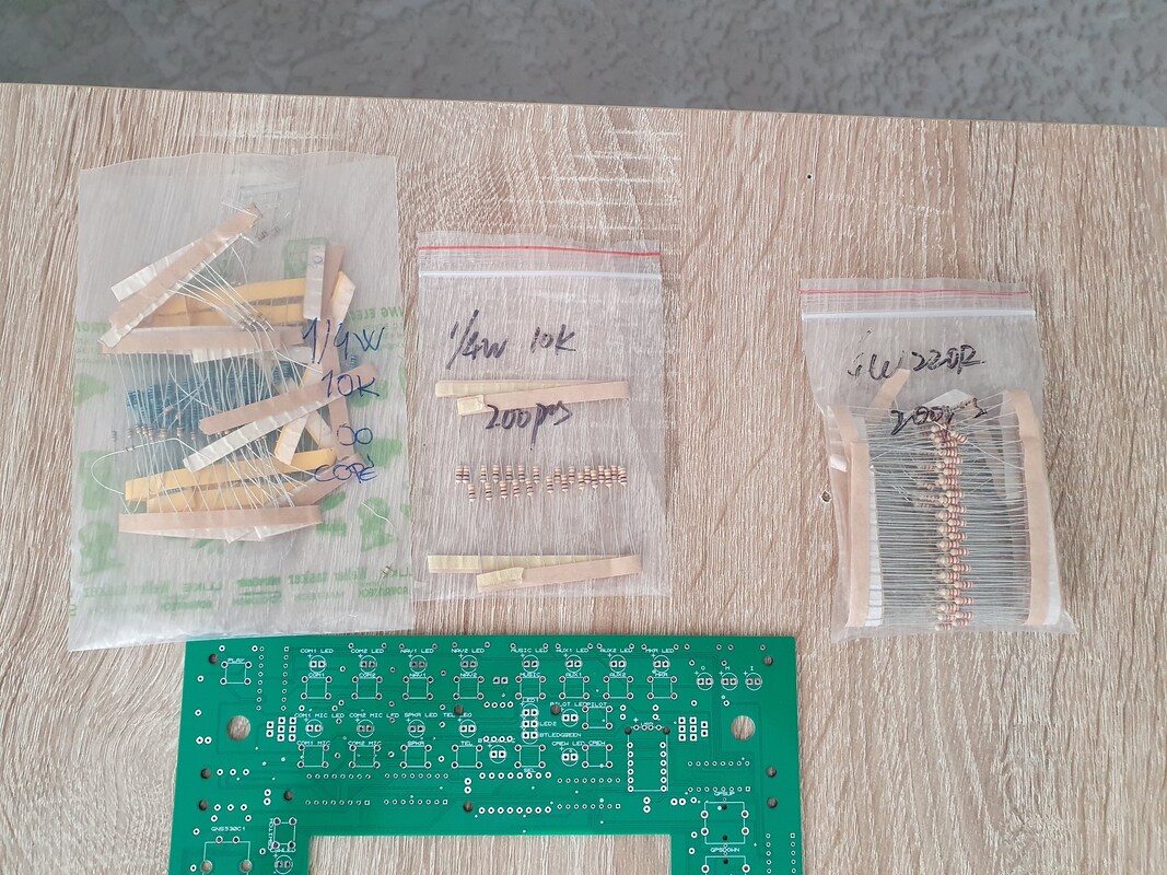
First we will start with the back of the board to solder the resistors,
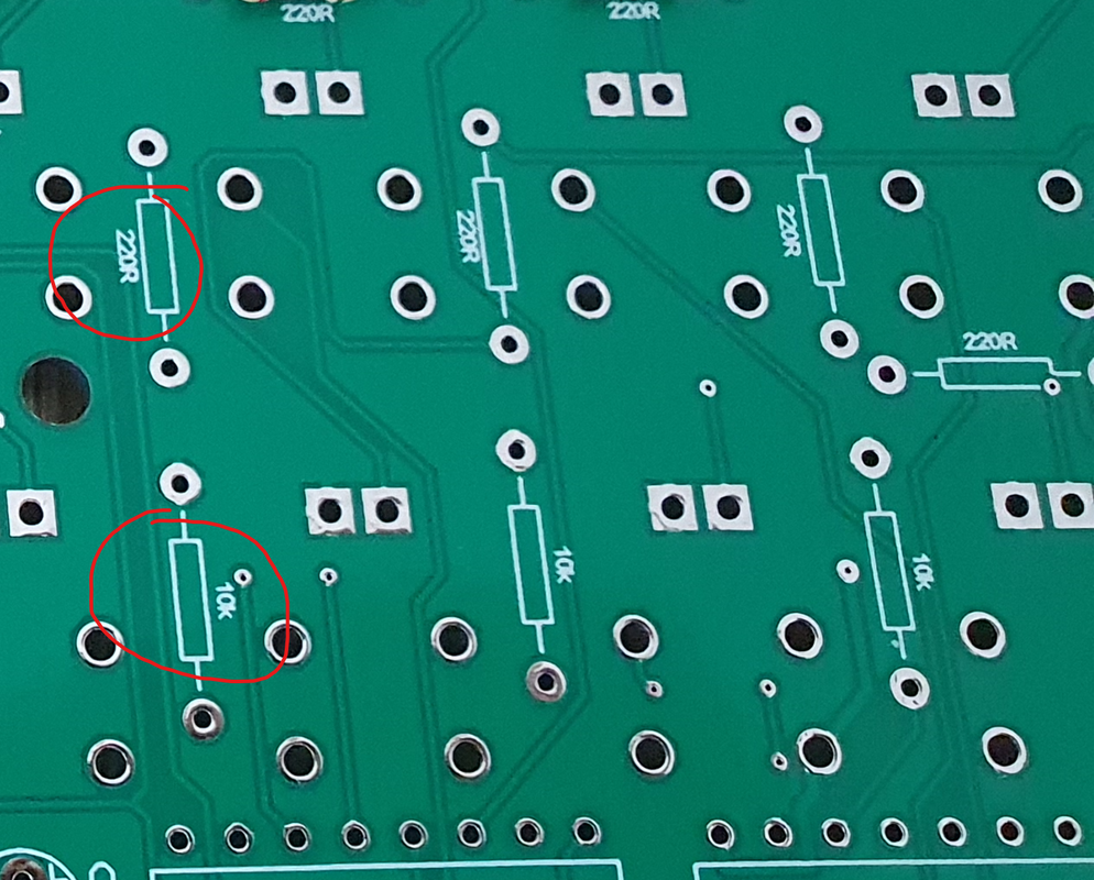
There are two types of resistors:
- 220R - which are 220 Ohm resistors ( 84 pcs) and
- 10K - which are 10 Kohm resistors ( 97 pcs)
Both resistor types are labeled on the back of the board.
First we will start with the back of the board to solder the resistors,
There are two types of resistors:
- 220R - which are 220 Ohm resistors ( 84 pcs) and
- 10K - which are 10 Kohm resistors ( 97 pcs)
Both resistor types are labeled on the back of the board.
|
|
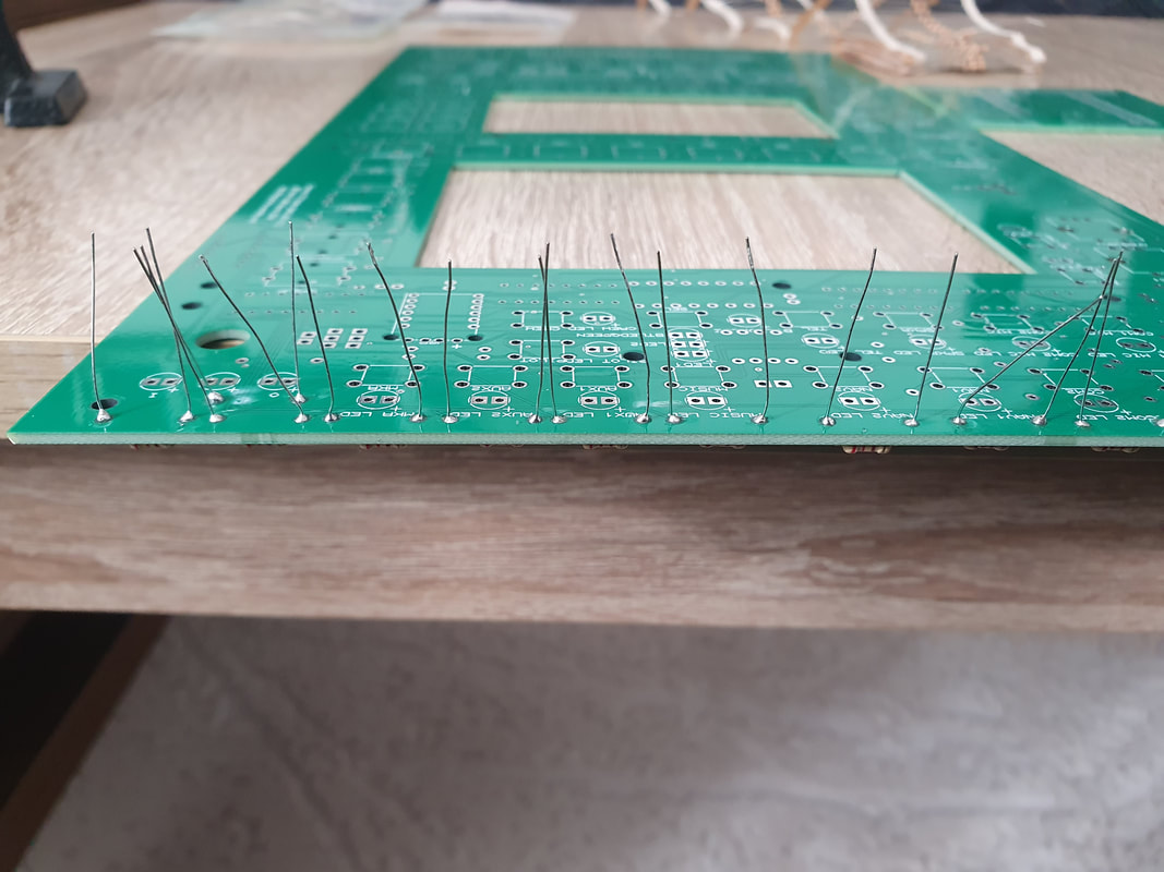
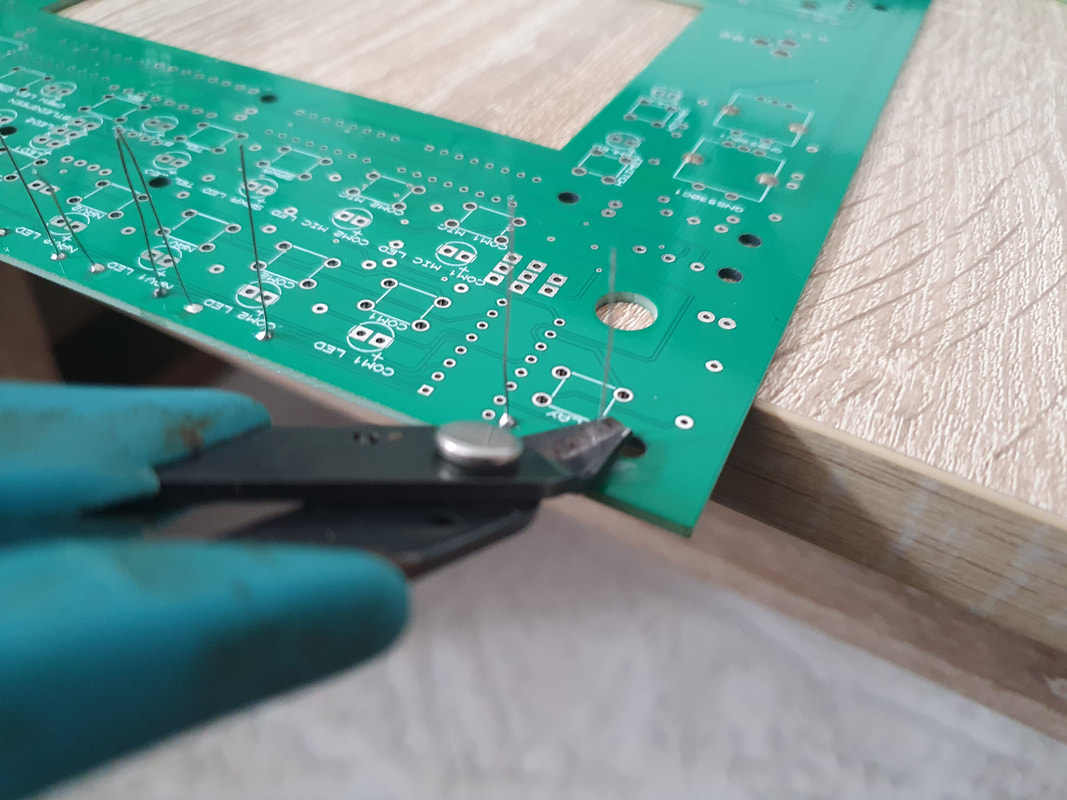
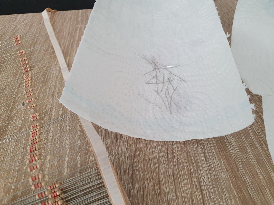
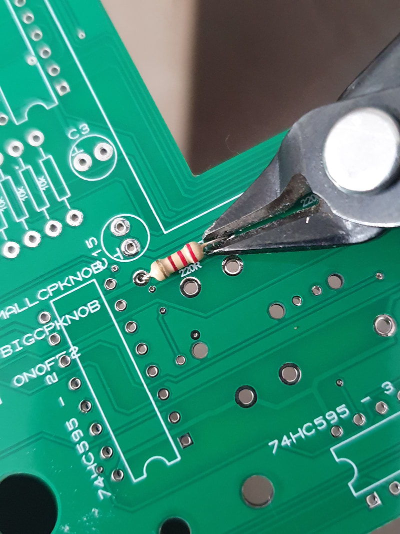
We will start with 220 Ohm and solder them all where labeled. Start from the top by putting few resistors in place, using the edge of the table, bend them underneath a little bit so when you flip the pcb to solder them, they won't fall out. After soldering them, cut them carefully, by holding the pins with one hand, and cut with the other, so they don't jump all over the place which can be dangerous if you step on them. Use something to throw them together.
|
|
|
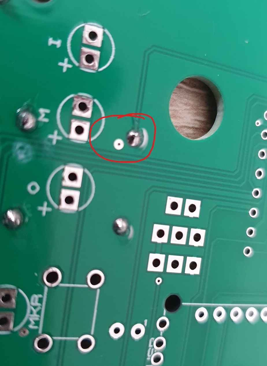
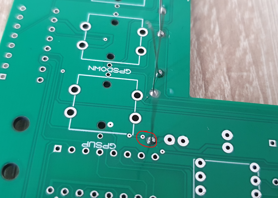
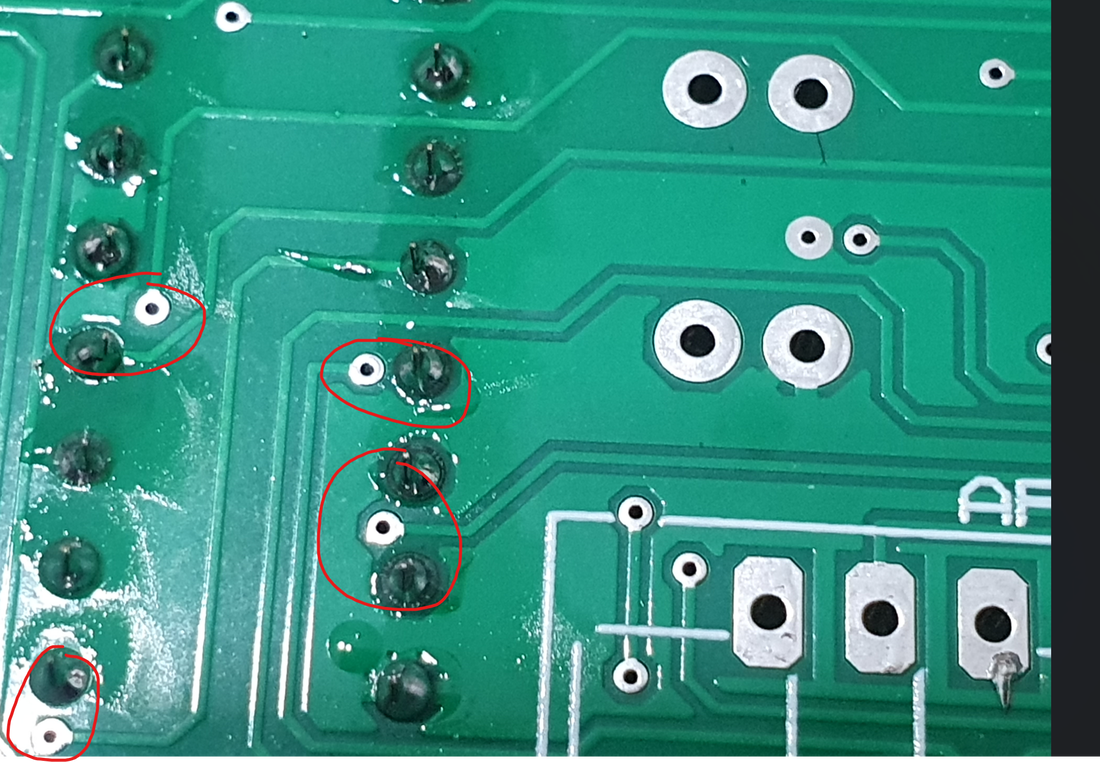
When soldering the components, please be very carefull for small pads near the pins that you need to solder. You need to be carefull with these through the entire process of soldering the components. If you are unsure, take a magnifying glass or use your phone's camera and zoom in, it will work great.
|
|
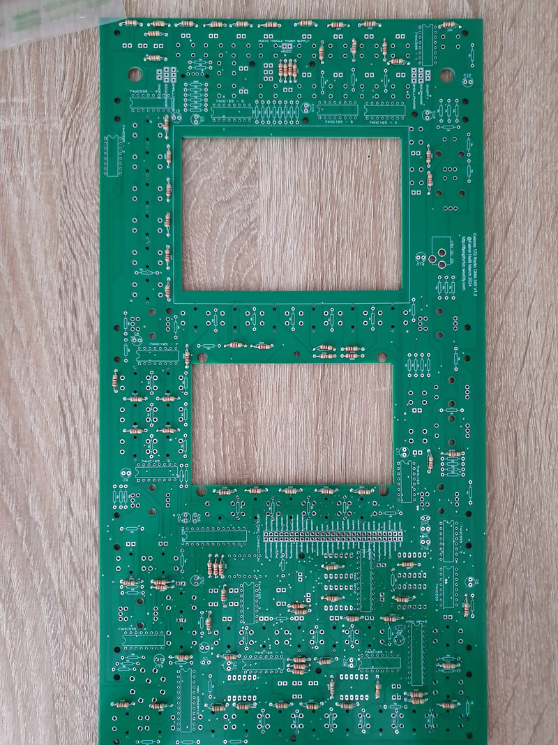
Once we finish with 220 Ohm resistors, here are the results:
Now we do the same with the 10K resistors. After completing them all, here is the final result with all resistors soldered in place. (On the picutre below, don't judge the resistors type by the color, because I have used two types from 10k which are blue and white)
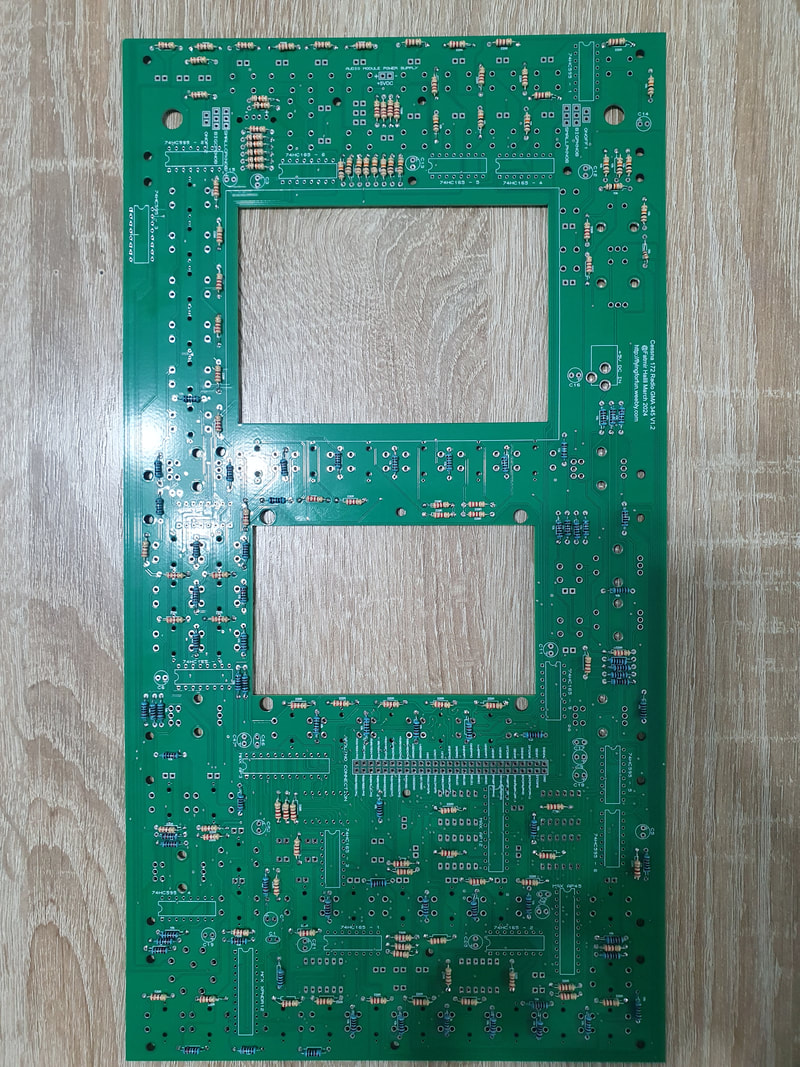
After installing all the resistors, please inspect them one more time. If by mistake you have soldered a wrong resistor, just cut the wrong one, cut the correct one to size and solder from above. This won't be difficult, as there is already solder in the holes.
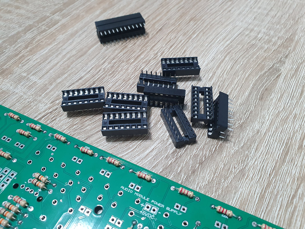
Next we will be soldering the shift register sockets. I strongly recommend to use these sockets and NOT solder the chips directly to the board. Using the sockets will be much easier to swap them in case you have a bad one or they get damaged.
There are two types of IC sockets that we need:
24 pin DIP narrow IC sockets - for the Max7219 chips (4 pcs) and
16 pin DIP IC sockets - for 74HC165 and 74HC595 shift registers (15 pcs)
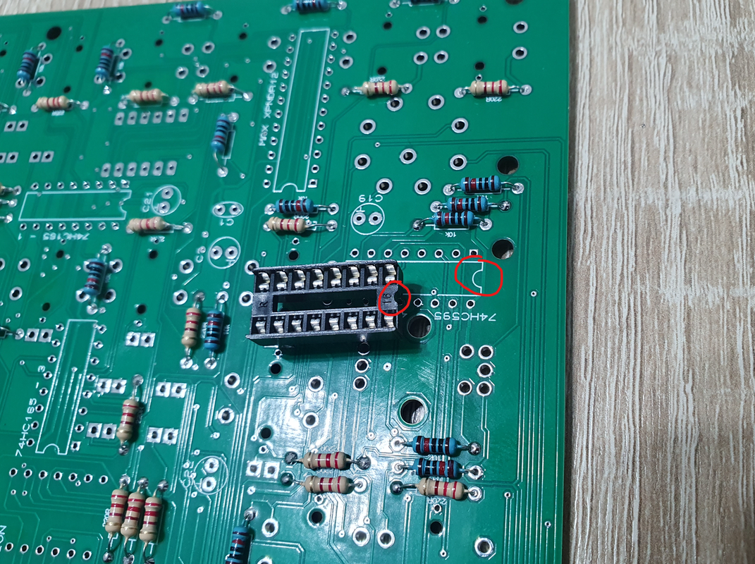
When soldering the sockets, we need to make sure to install them correctly by matching the arc of the socket with the arc on the PCB (see the middle picture). Installing them the oposite direction might cause damage to the shift registers or other components.
Here we also need to be very carefull with the pads that are near the pin where you need to solder. Don't short them. You just need to hold the soldering iron on the oposite side of the pin to heat it and once heated, the solder will automatically go the the pin.
There are two types of IC sockets that we need:
24 pin DIP narrow IC sockets - for the Max7219 chips (4 pcs) and
16 pin DIP IC sockets - for 74HC165 and 74HC595 shift registers (15 pcs)
When soldering the sockets, we need to make sure to install them correctly by matching the arc of the socket with the arc on the PCB (see the middle picture). Installing them the oposite direction might cause damage to the shift registers or other components.
Here we also need to be very carefull with the pads that are near the pin where you need to solder. Don't short them. You just need to hold the soldering iron on the oposite side of the pin to heat it and once heated, the solder will automatically go the the pin.
|
|
|
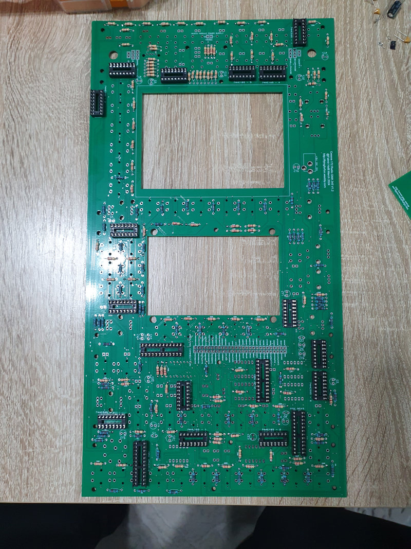
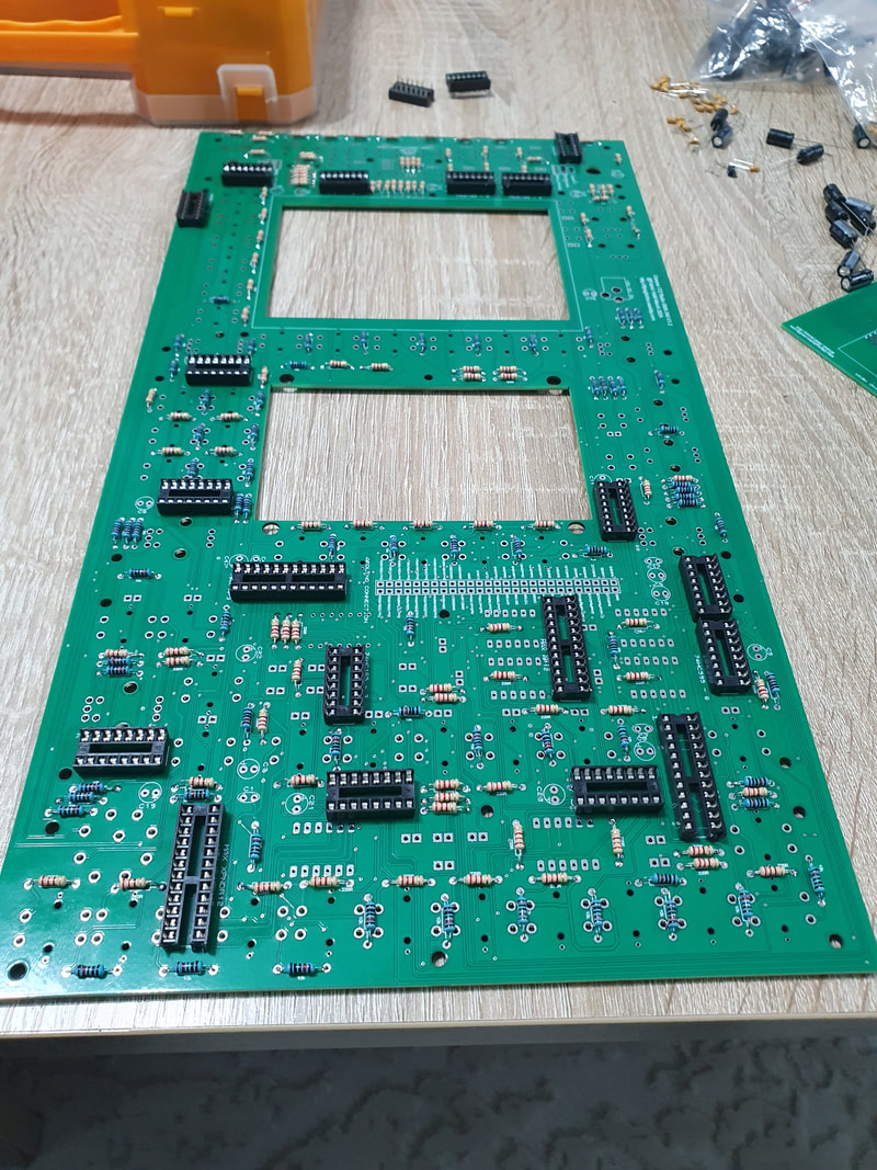
Once finished, this will be the result
|
|
Now let start soldering the capacitors. There are two types we will need:
25v 10uF electrolytic capacitors (the big black and brown ones, 13 pcs) and
50v 0.1uF ceramic capacitors (the small yellow ones, 6pcs)
25v 10uF electrolytic capacitors (the big black and brown ones, 13 pcs) and
50v 0.1uF ceramic capacitors (the small yellow ones, 6pcs)
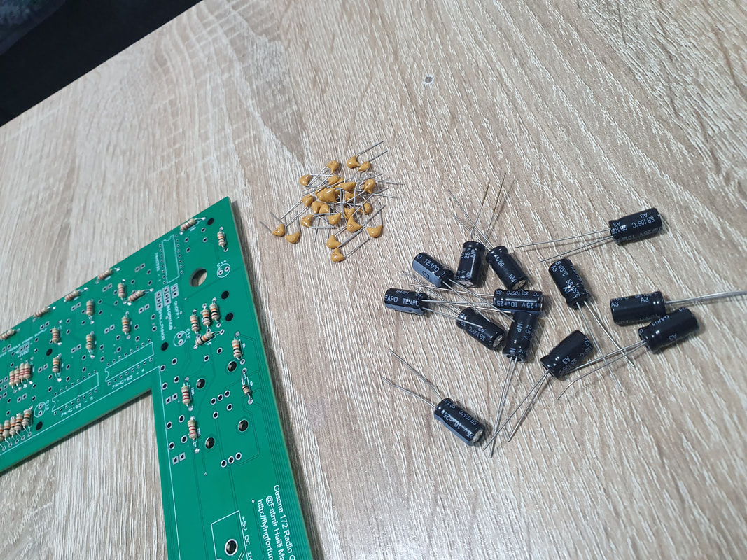
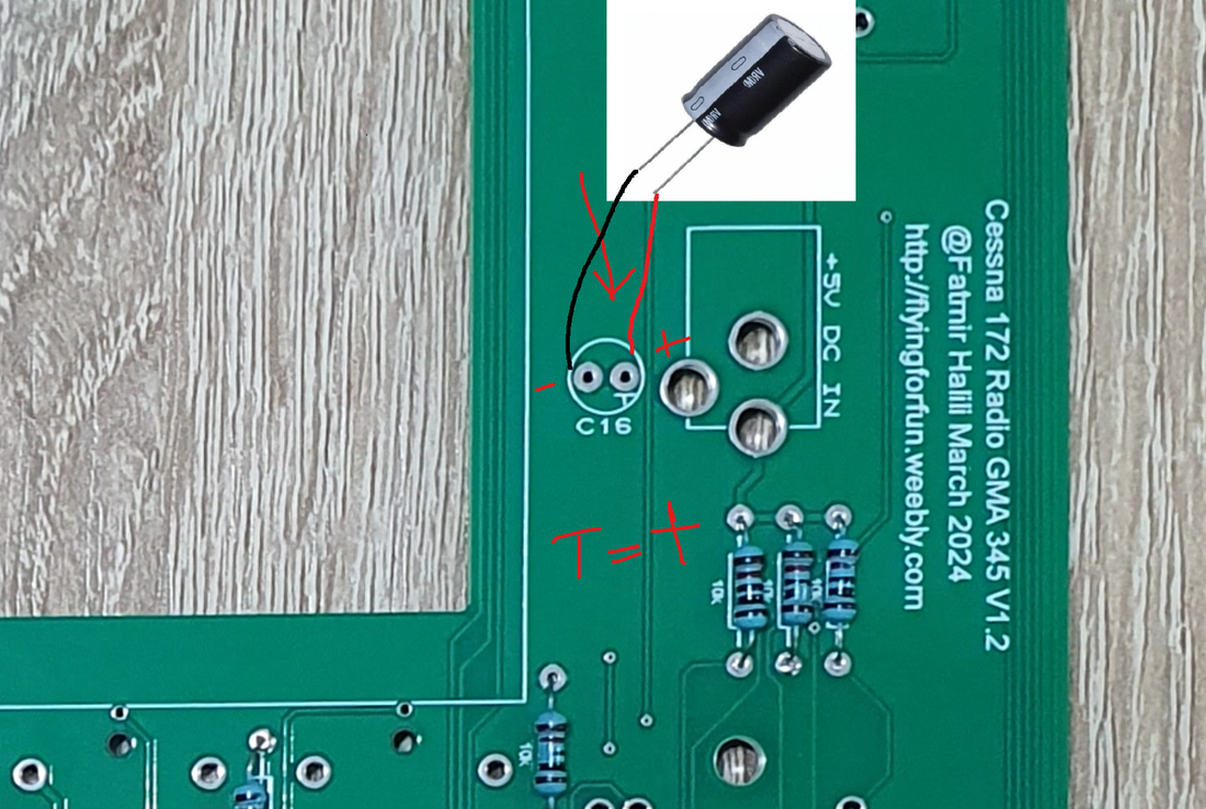
When installing the 25V 10uF electrolytic capacitors, we need to watch the polarity and solder them in the right way. Not doing so may cause damage to them or other components.
These capacitors have a minus sign on the brown color, which indicates the negative side of the capacitor. This means the pin on this side, will need to go to the pin on the PCB where is no sign at all (it is blank). There is only one sign that it looks like letter T, but which in fact is + sign, where the upper part was unfortunately not printed because of the pads. This means T is positive, blank side is negative.
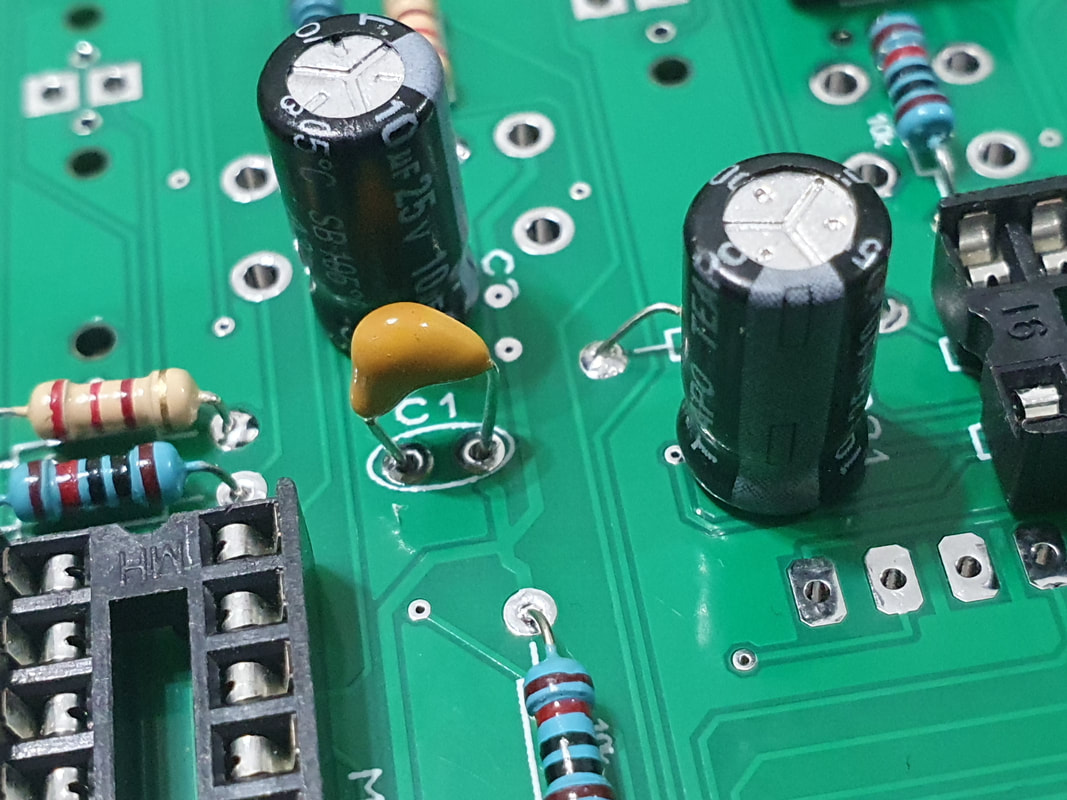
The ceramic capacitors (yellow ones) have no polarity, so we can install them any way we want.
These capacitors have a minus sign on the brown color, which indicates the negative side of the capacitor. This means the pin on this side, will need to go to the pin on the PCB where is no sign at all (it is blank). There is only one sign that it looks like letter T, but which in fact is + sign, where the upper part was unfortunately not printed because of the pads. This means T is positive, blank side is negative.
The ceramic capacitors (yellow ones) have no polarity, so we can install them any way we want.
|
|
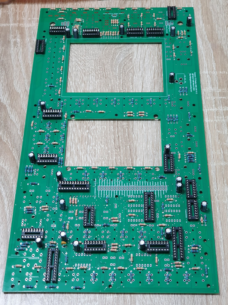
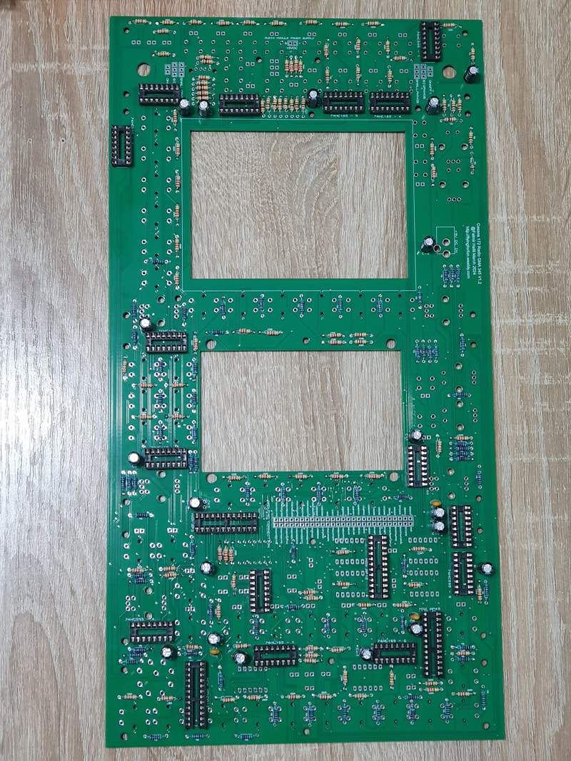
Step by step, the board gets more and more populated. Here are the results after installing the capacitors.
|
|
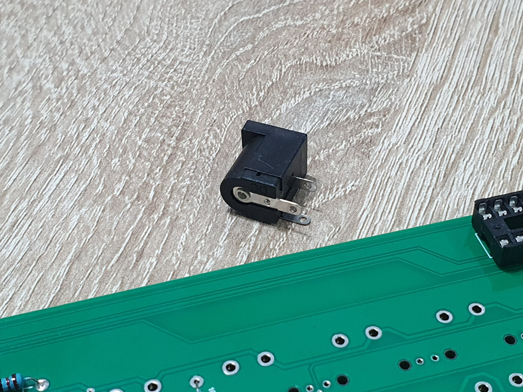
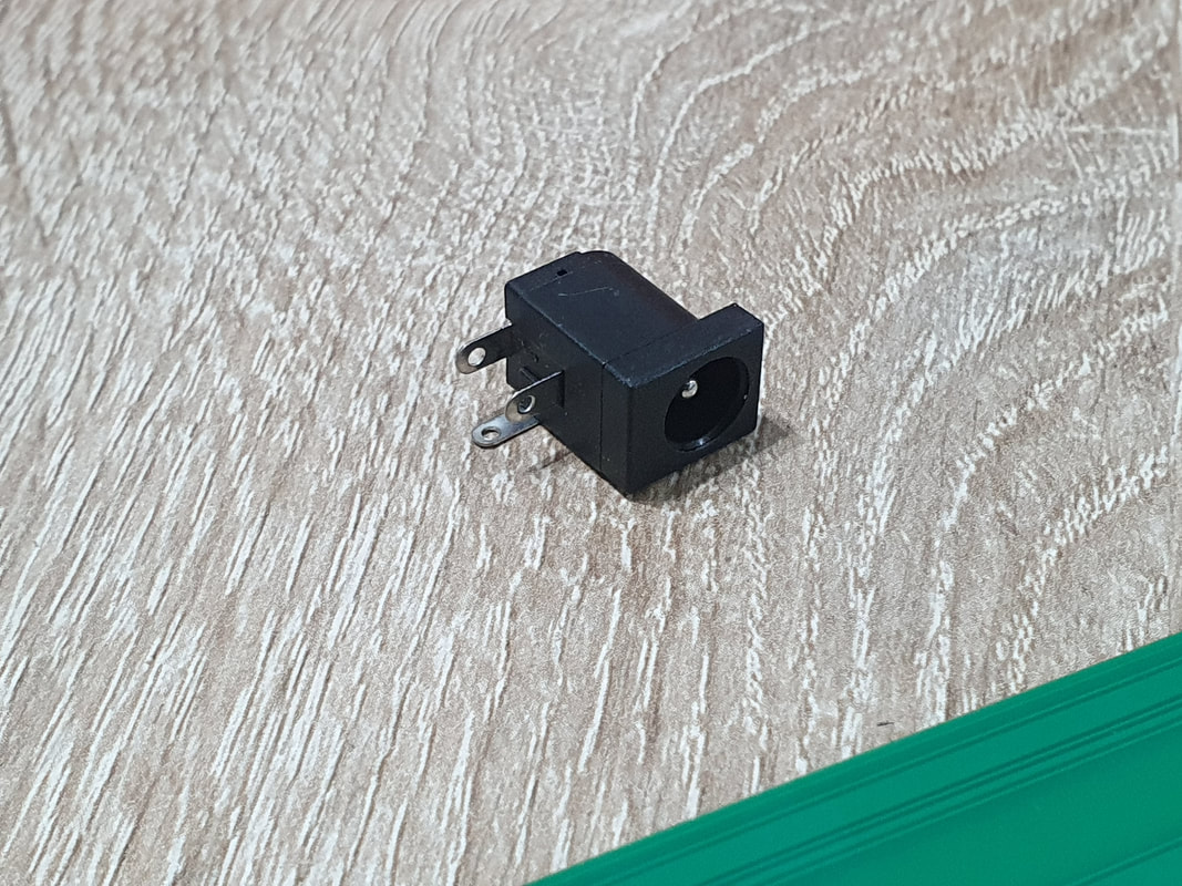
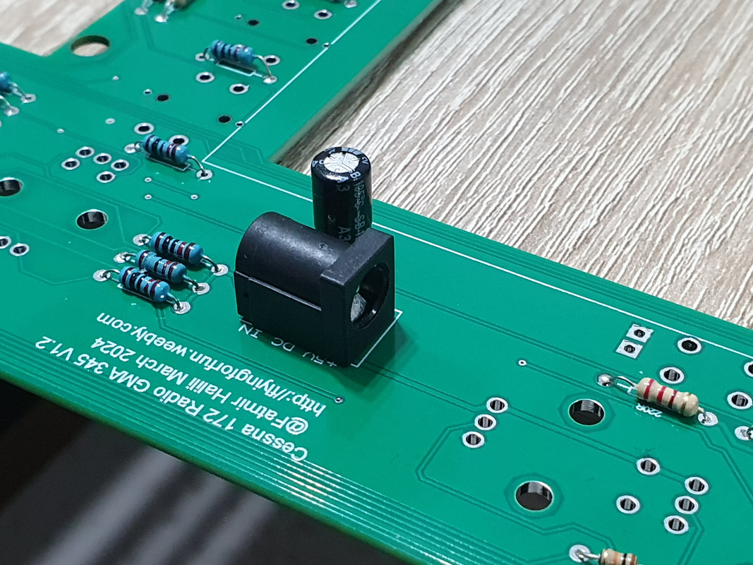
Next let's install the power supply connector. We put the connector in place and solder it. Here we may need to hold the soldering iron a bit longer to heat the connector pins which are bigger than other pins we have soldered so far.
|
|
|
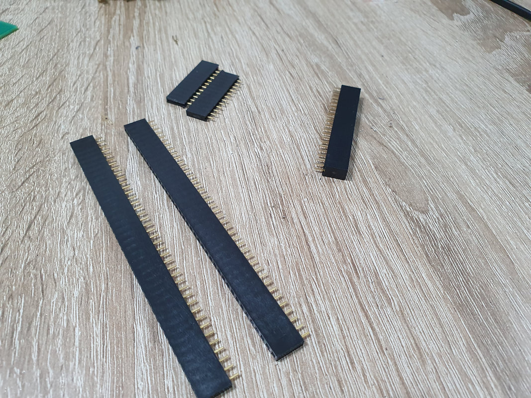
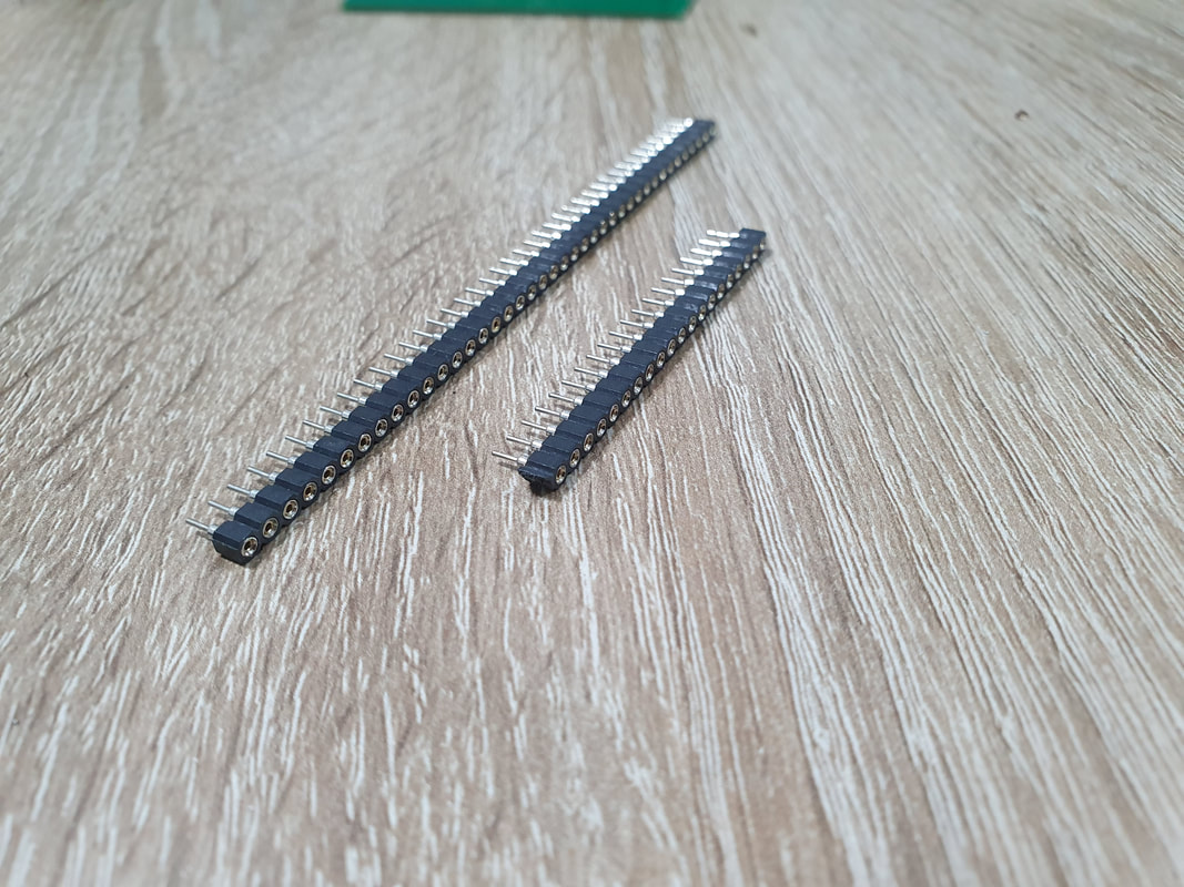
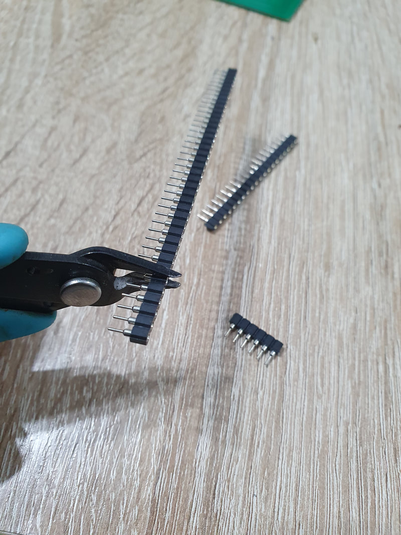
With the connectors done, it is time to solder the female pin headers. We will need these to connect the arduino shield to the PCB. The shield needs 54 pins, which means 2 raws with 27 pins each. If you have 27 pin headers, just put them in place and solder. If you have longer ones, just cut them to size ( when cutting please be carefull to cut one pin longer, because if you cut exactly, most of the time the last pin gets out of the place).
|
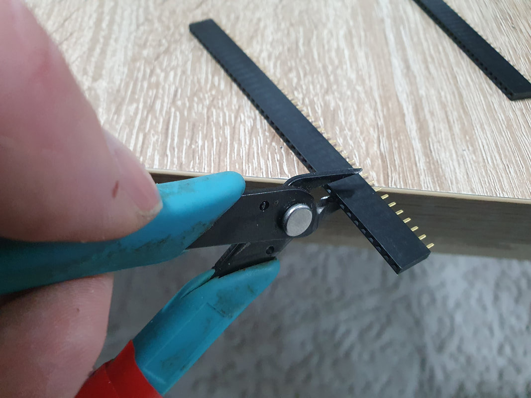
|
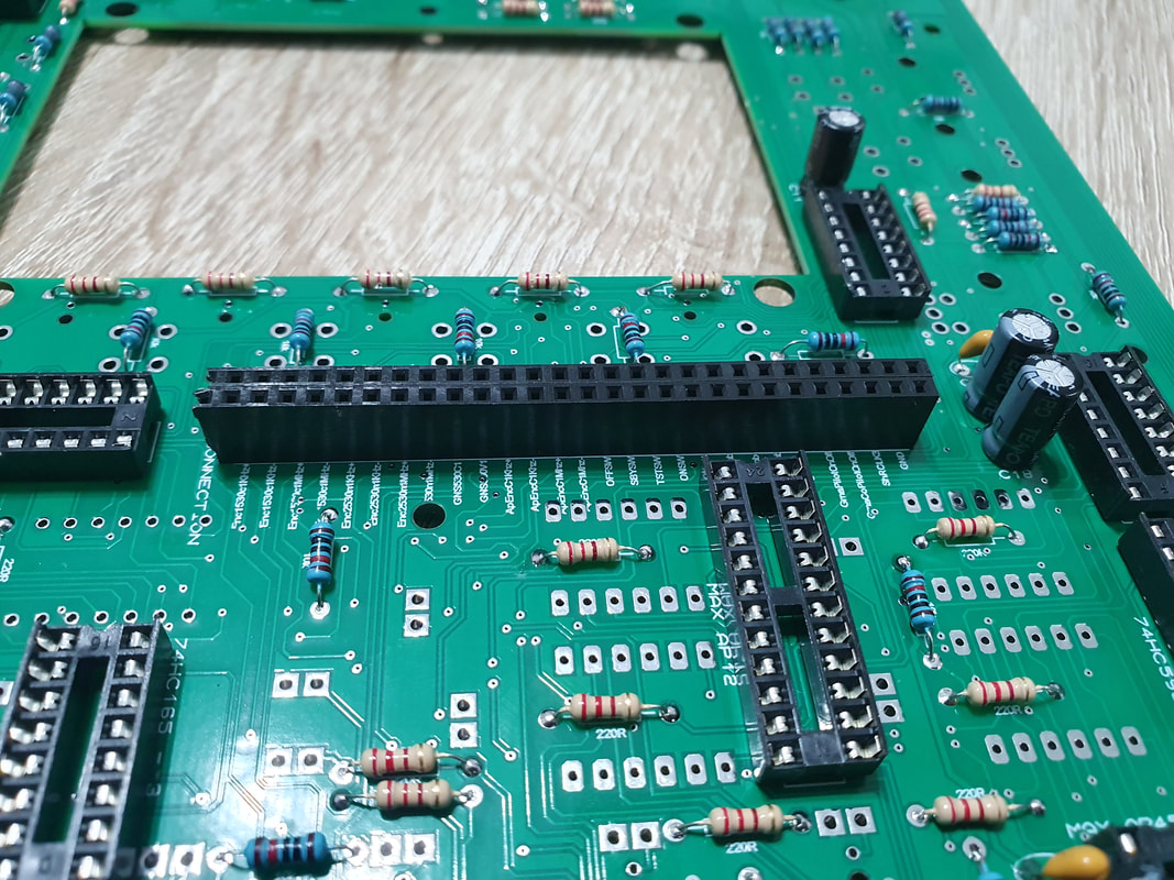
|
The last thing we will be soldering on the back side, will be the male pin headers, which we will need to connect the volume potentiometers to. These are located at the top of the PCB where the GMA 345 components are. We cut the pin headers to 2x3 pin + 1x2 pin for each side (two sides in total) and solder them in place.
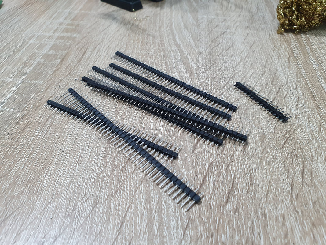
|
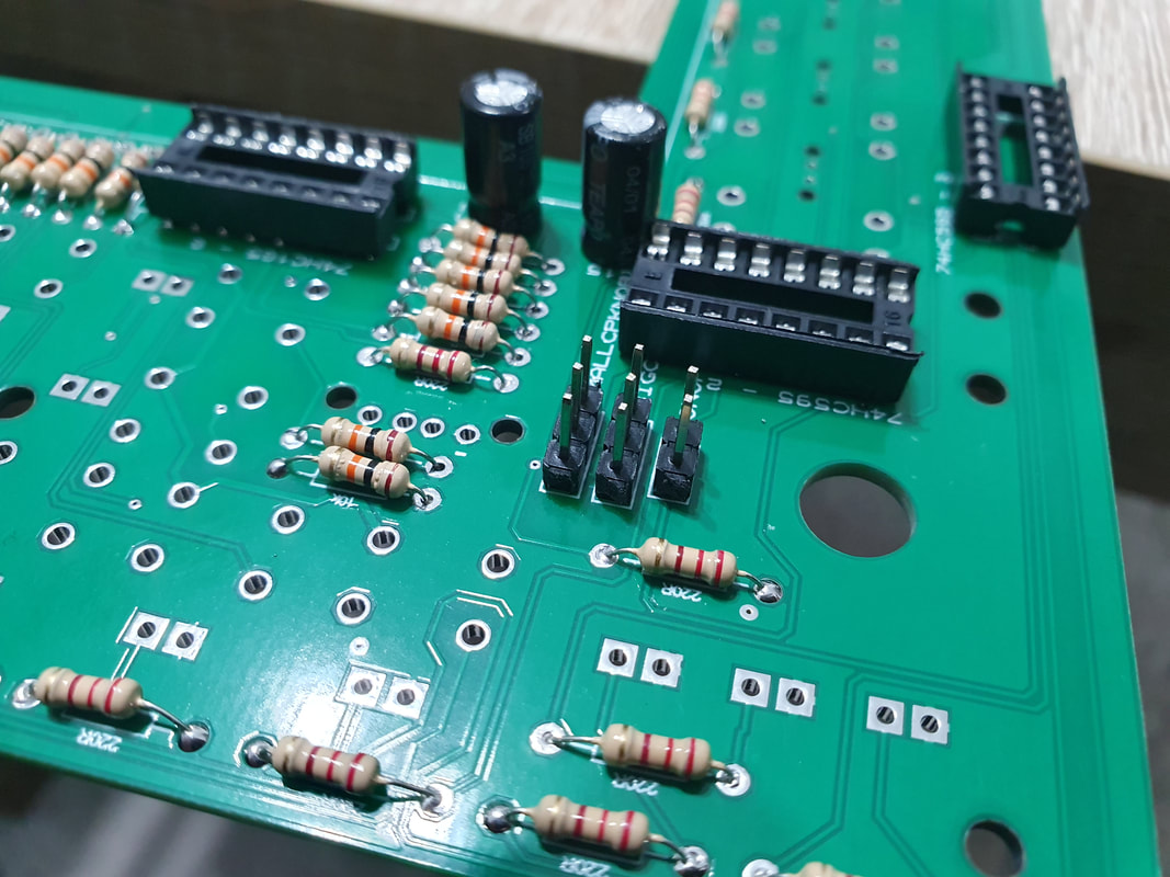
|
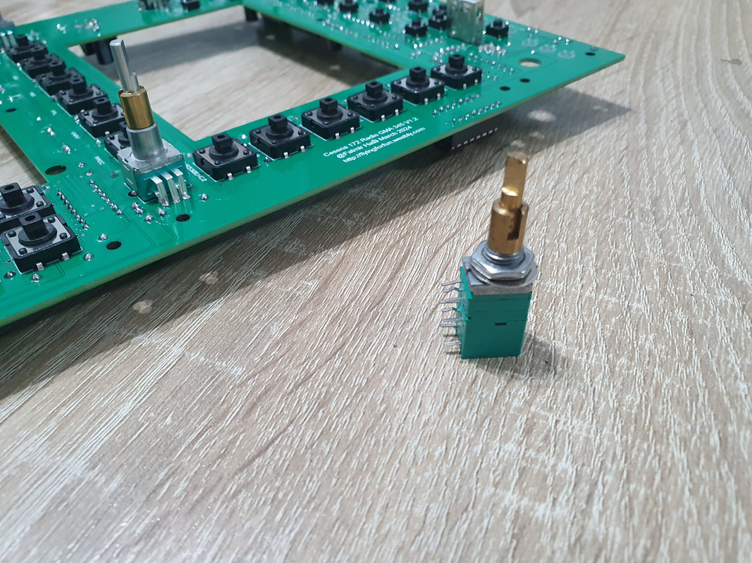
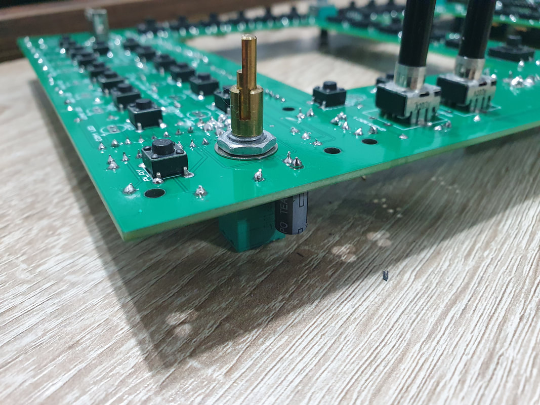
After soldering the components, we can go ahead and mount the two double potentiometers with switch. We place them from beneath the pcb in the deditacted holes and tighten them with the provided nuts. You need to cut a small pin that is on the potentiometer under the nut, so it can sit flat on the surface of the pcb.
|
|
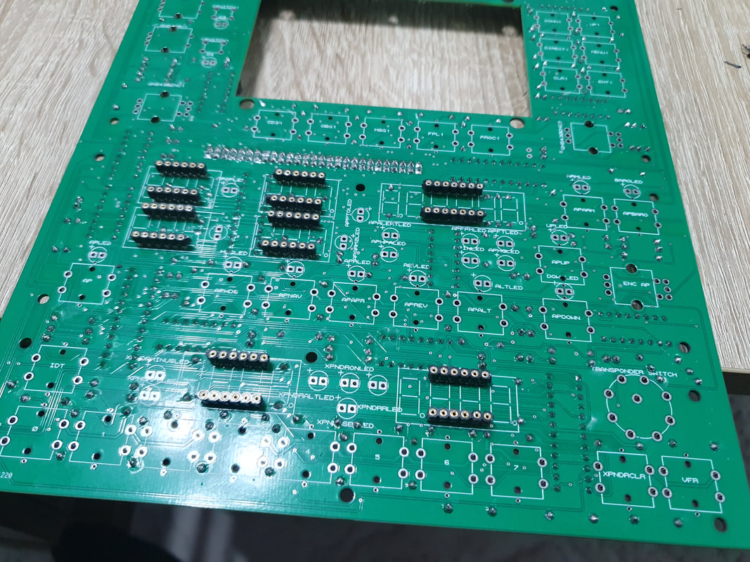
Now we are done with the back side of the PCB, so we flip it around and start with th round female headers for the displays. I also strongly recommend to use these, for the same reasons as the IC sockets.
When installing the round female headers, we need to make sure that they are sitting firmly in place and are not in any ways standing not streight, because in that case we won't be able to put the 7 segment displays. The best way would be to:
1. Cut them to size
2. insert them into the 7 segment display pins
3. solder them to place with the 7 segment display attached to them
This way when they are soldered, they will have the perfect form of the 7 segment displays so we can remove them and put them back easily.
When installing the round female headers, we need to make sure that they are sitting firmly in place and are not in any ways standing not streight, because in that case we won't be able to put the 7 segment displays. The best way would be to:
1. Cut them to size
2. insert them into the 7 segment display pins
3. solder them to place with the 7 segment display attached to them
This way when they are soldered, they will have the perfect form of the 7 segment displays so we can remove them and put them back easily.
|
|
|
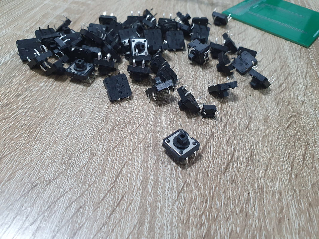
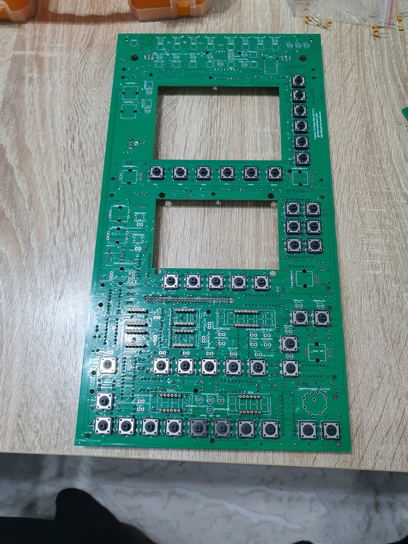
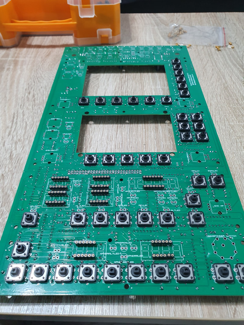
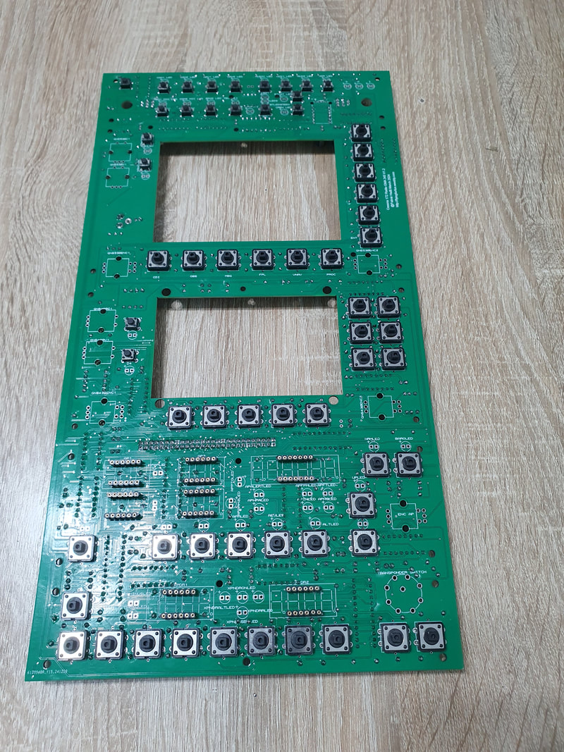
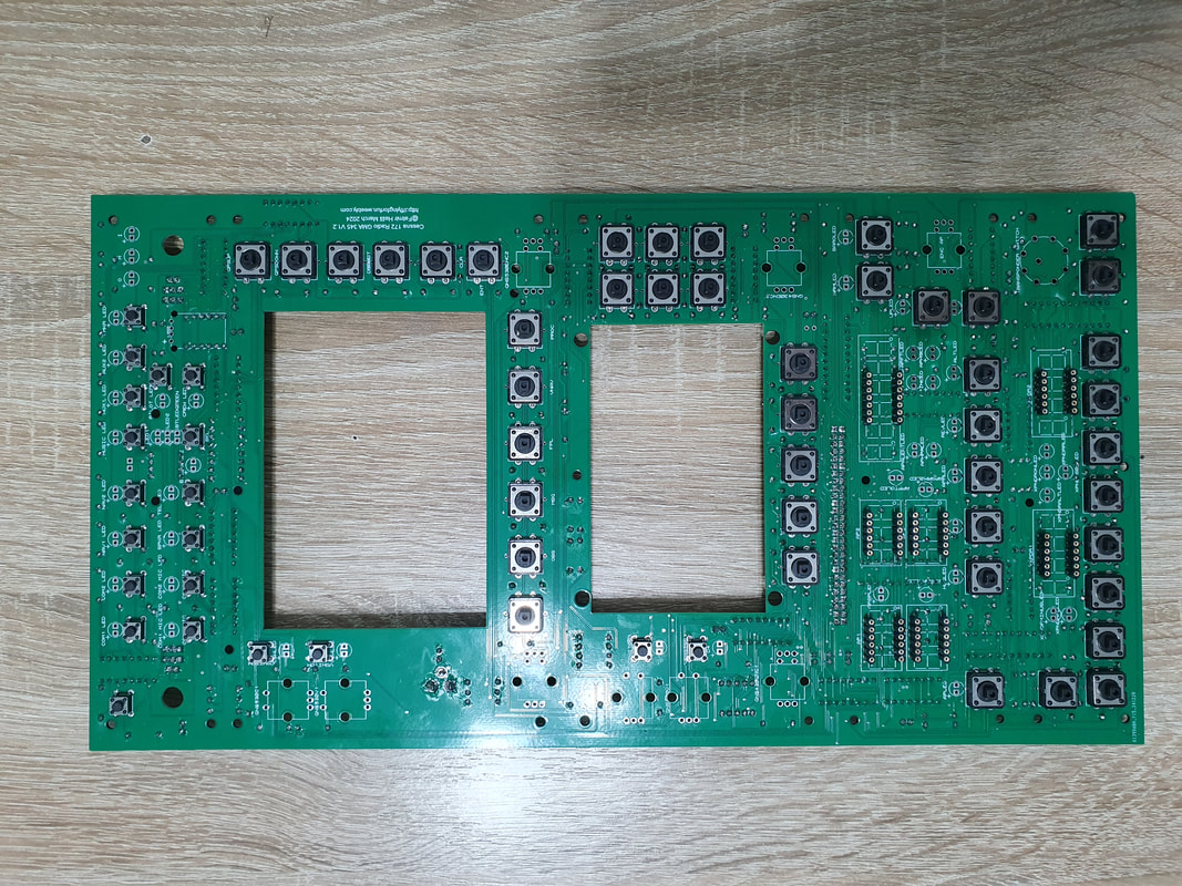
Next we will solder the tactile push buttons. We will start with the 12x12mm ones, put them in place. When soldering them, we need to make sure they are in a streight line with each other, otherwise it might cause us issues with the alignement of the 3d printed buttons.
|
|
|
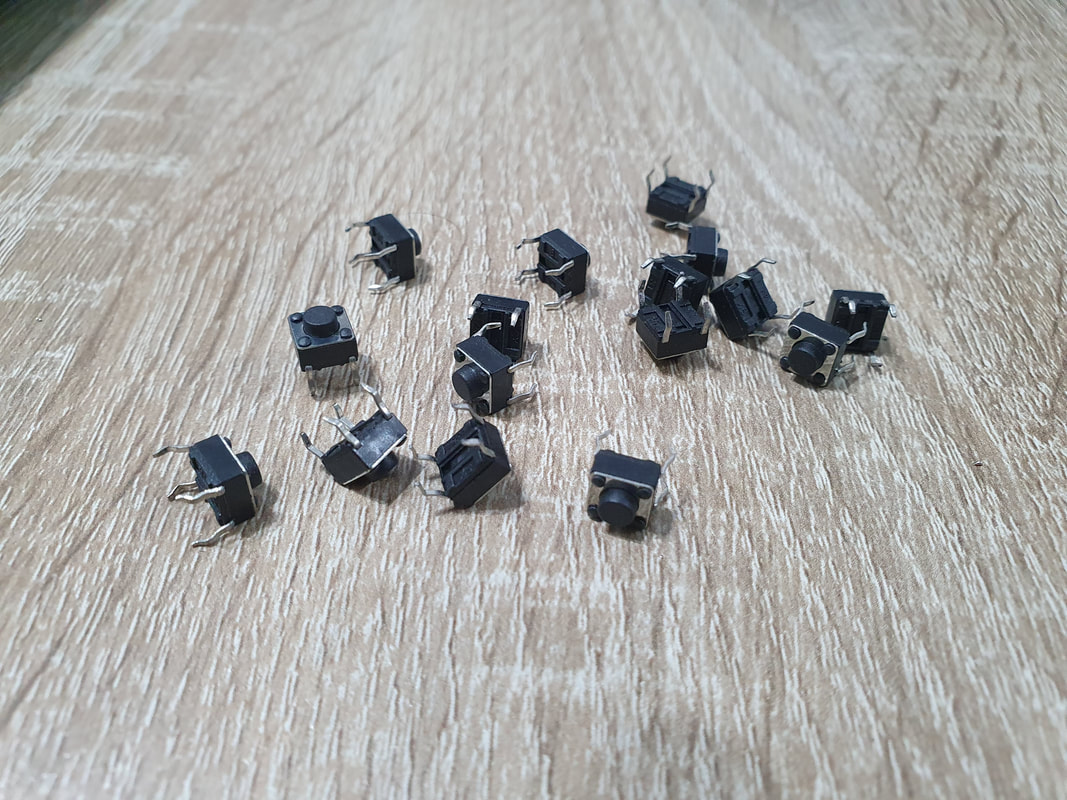
We do the same with the 6x6 mm push buttons.
|
|
|
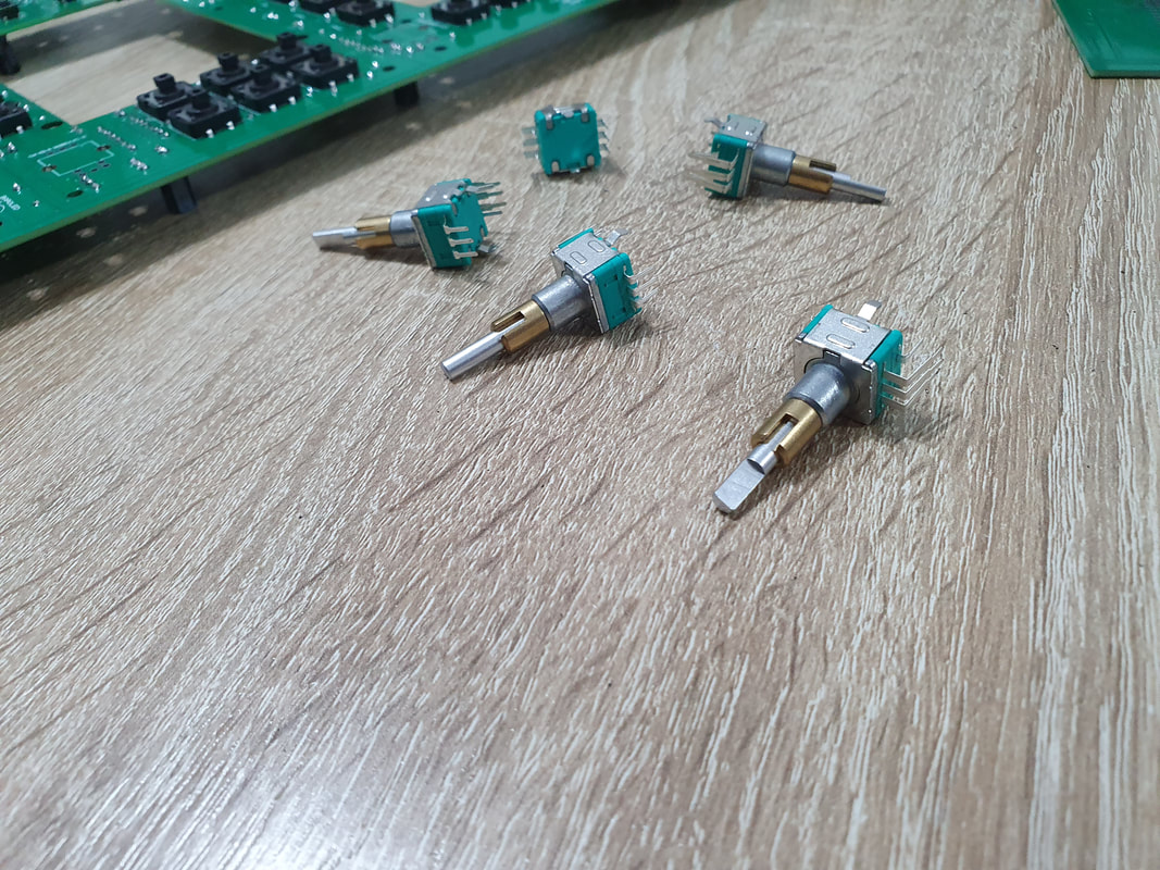
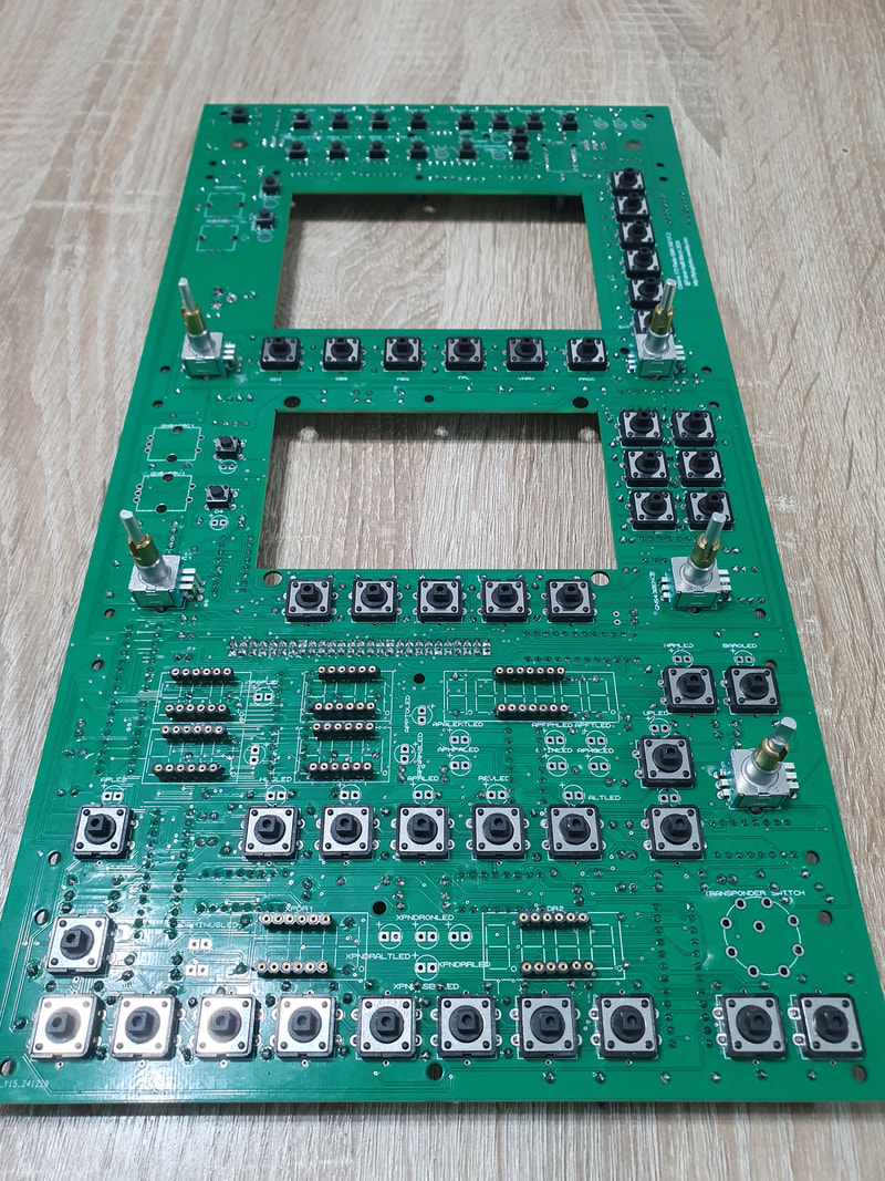
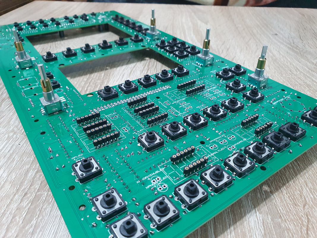
We continue with the installation of the dual concentric encoders. We have 5 pcs that we need to solder to the board one by one. We need to make sure they sit properly on pcb when soldering.
|
|
|
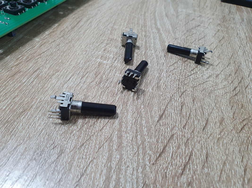
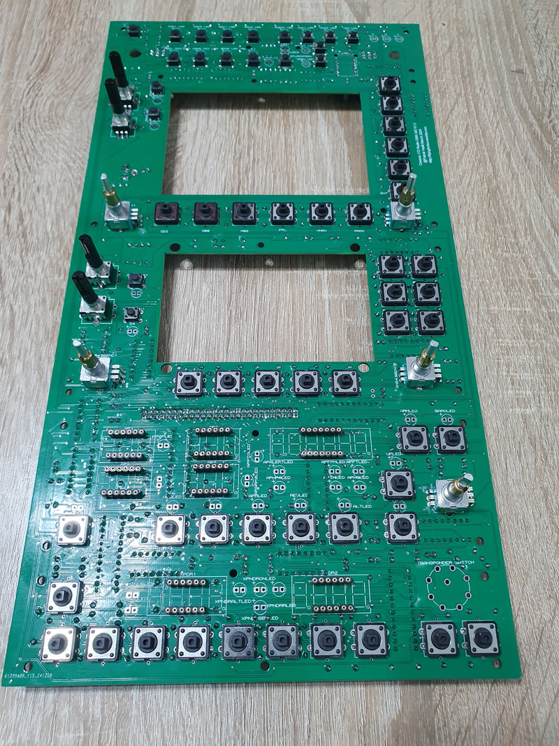
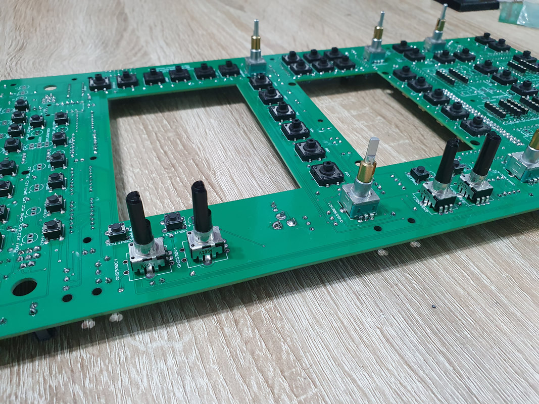
Next are the potentiometers for the GNS 530 and GNS 430 Volumes
|
|
|
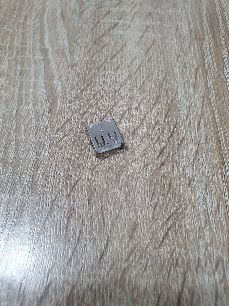
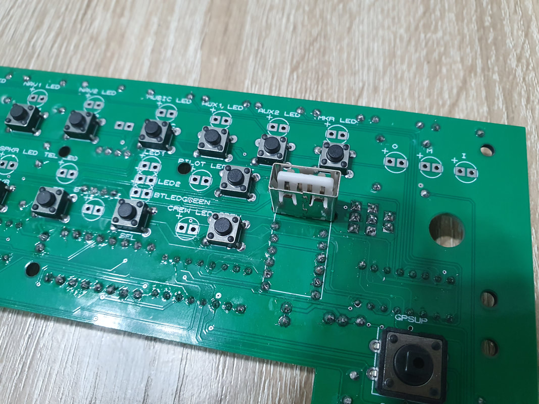
The GMA 345 has a USB port. In order to mimic the original, I added a USB port type A here as well which I connected to +5V main rail of the PCB, which means it will provide you with 5V power to charge the phone. I would not recommend to use it though, it should be there more for aesthetics.
|
|
Arduino Shield
Now it is time to start assembling the Arduino shield. Here we will need two types of pins that we need to solder.
90 degrees double headed male pins to connect the shield to the main PCB
Female pins for the attachment of Arduino Mega 2560 Pro mini and
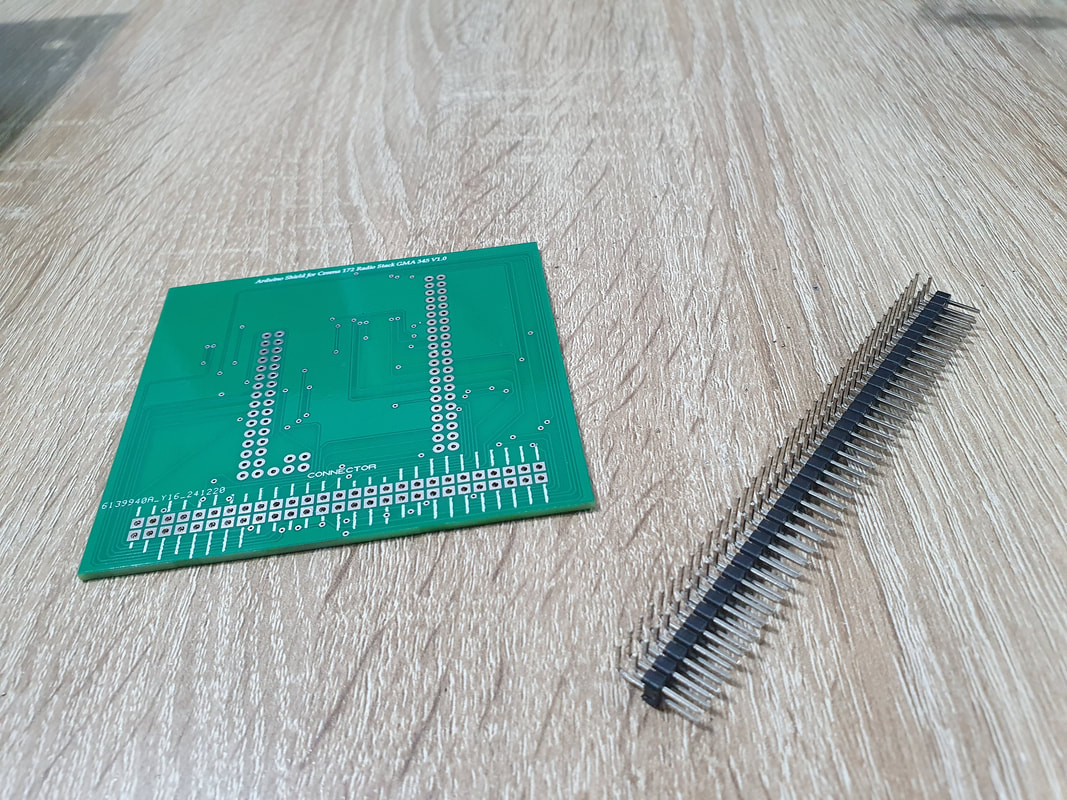
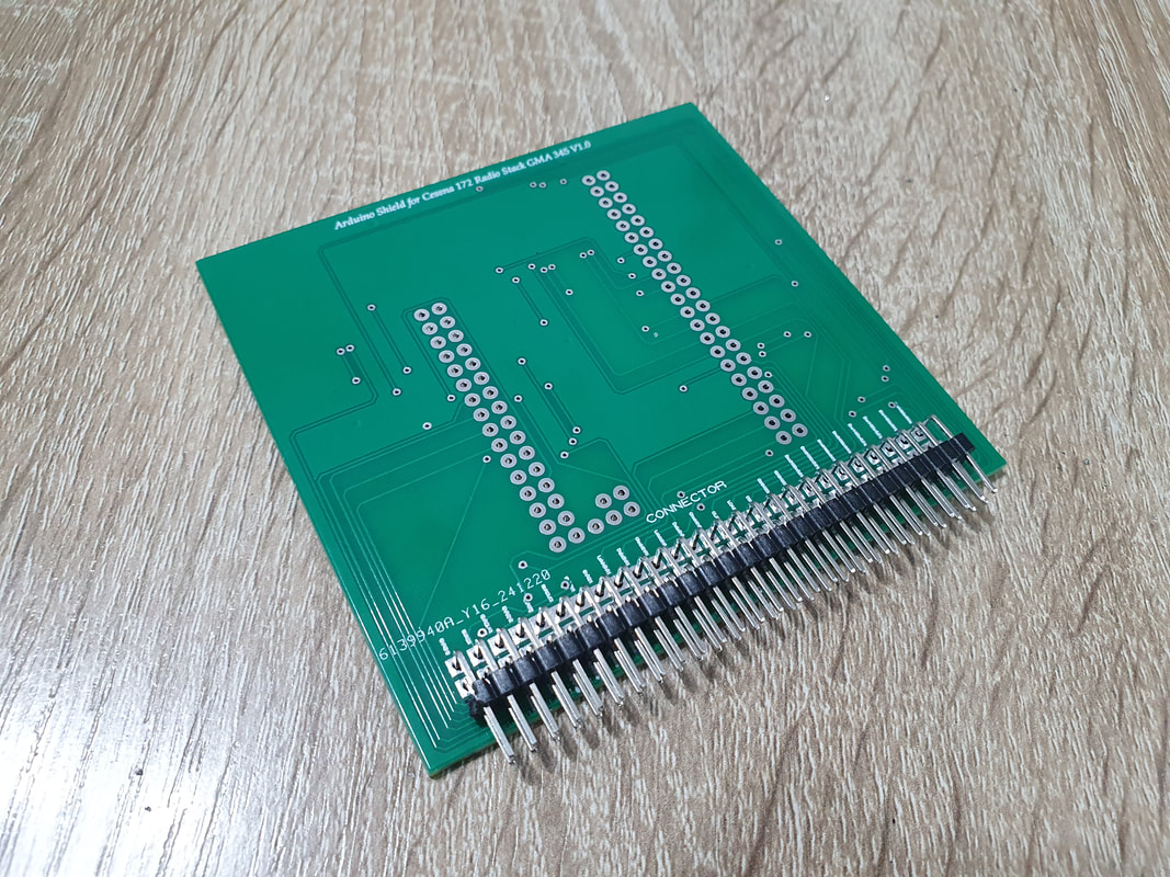
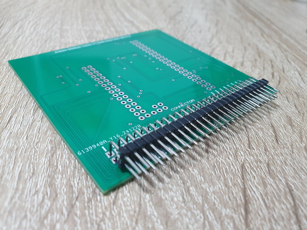
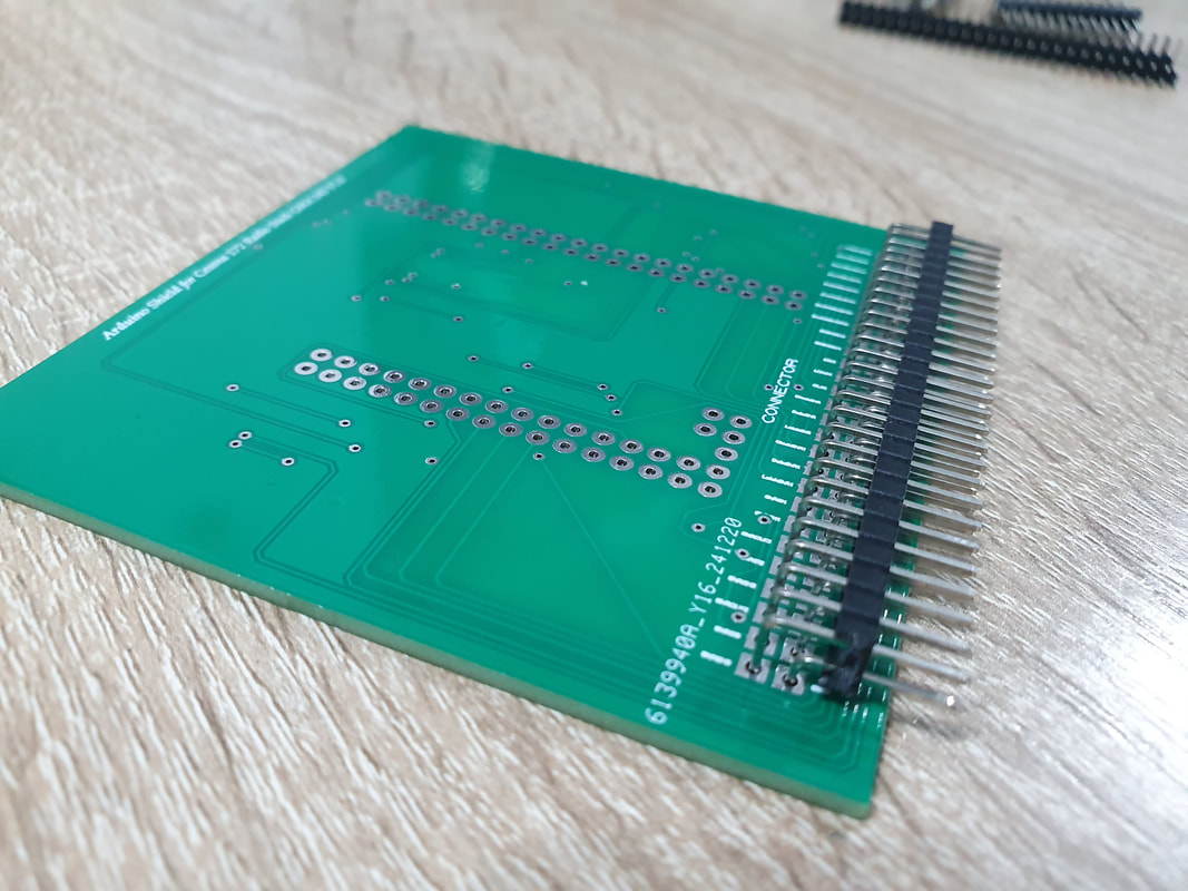
We will start with the double headed 90 degree male pins. we cut them to size, same as the female pins we cut ealier. The shield needs 54 pins, which means 2 raws with 27 pins each and insert them to the Arduino shield. As seen in the picture below, we place them on the side where it says CONNECTOR.
90 degrees double headed male pins to connect the shield to the main PCB
Female pins for the attachment of Arduino Mega 2560 Pro mini and
We will start with the double headed 90 degree male pins. we cut them to size, same as the female pins we cut ealier. The shield needs 54 pins, which means 2 raws with 27 pins each and insert them to the Arduino shield. As seen in the picture below, we place them on the side where it says CONNECTOR.
|
|
|
|
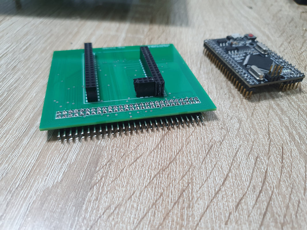
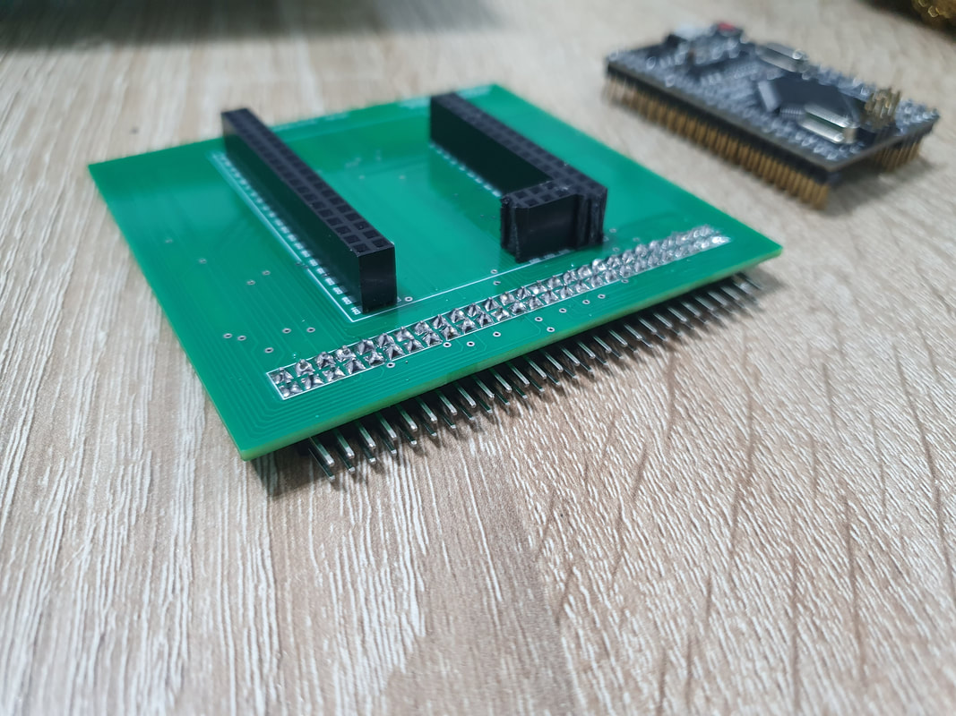
Once we solder them, we flip the board and cut the female pins to size and solder them onto the PCB
|
|
|
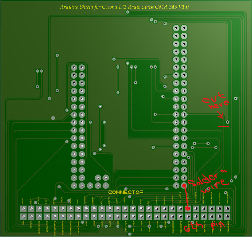
Now apparently for some reason, pin D13 on arduino doesn't work with rotary encoders, and exactly to that pin unfortunately I have connected the right encoder of GNS 430. This is present on Arduino shield V1. I have fixed this issue on arduino shield V1.1, but for those who have Arduino shield V1, you need to cut a trace and solder a wire. It is an easy fix, so we basically are changing Pin 13 of arduino with pin 31 which is unused. Below a picture explaining what you need to do.
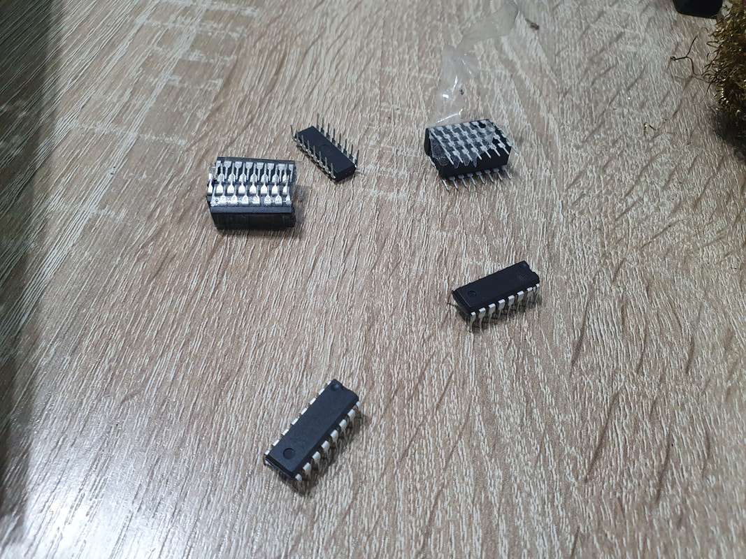
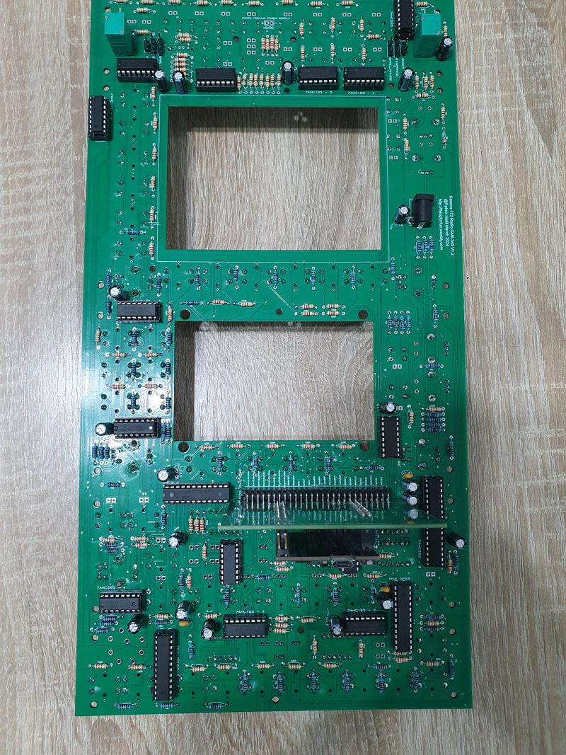
Now we will start to insert the shift registers in their places.
While doing that, we need to be careful again with the orientation. The arc on the shift register need to match the arc on the IC socket.
While doing that, we need to be careful again with the orientation. The arc on the shift register need to match the arc on the IC socket.
|
|
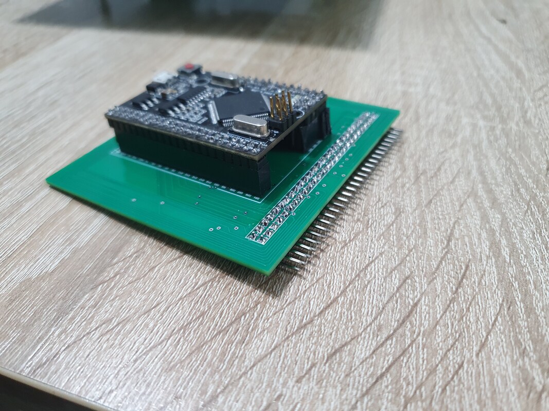
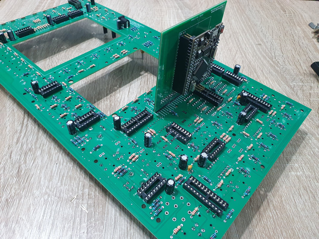
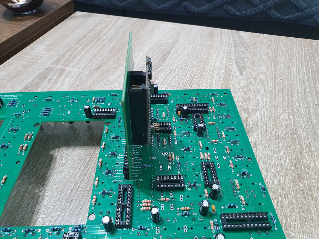
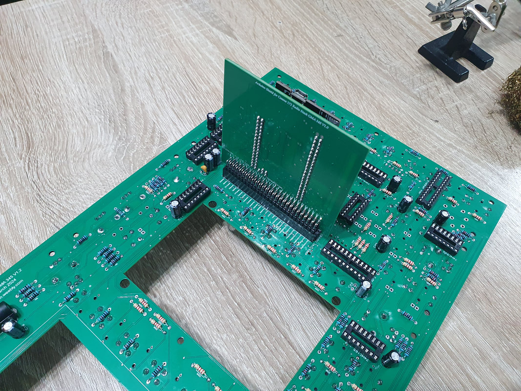
When we are done with the shift registers, we can go ahead and mount the arduino shield to the PCB. We mount the shield like in the pictures below, with the arduino laying down. When inserting the shield, we need to make sure we don't skip any pins to the left or right.
|
|
|
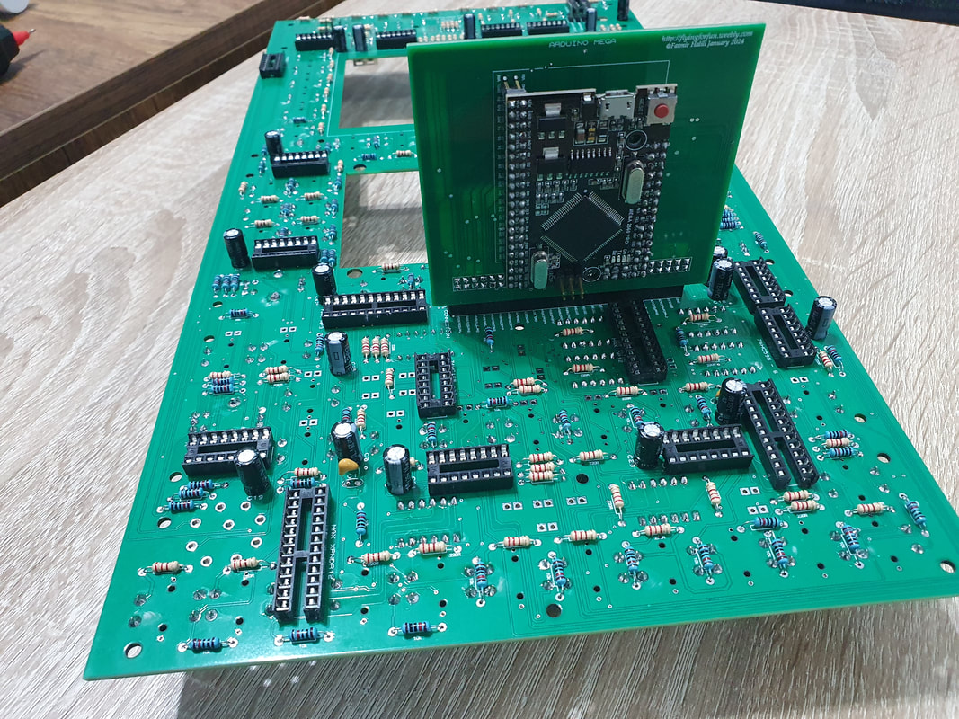
|
The last thing we will do now is to insert the 7 segment displays (4x3 digit, 2x4 digit and 1x6 digit). The displays need to be Common Cathode, otherwise they won't work. Later we will cut the pins of the 7 segment displays shorter, but for now we just insert them as they are to test the radio. We can also install now the 11mm spacers in the respective places like in the pictures below.
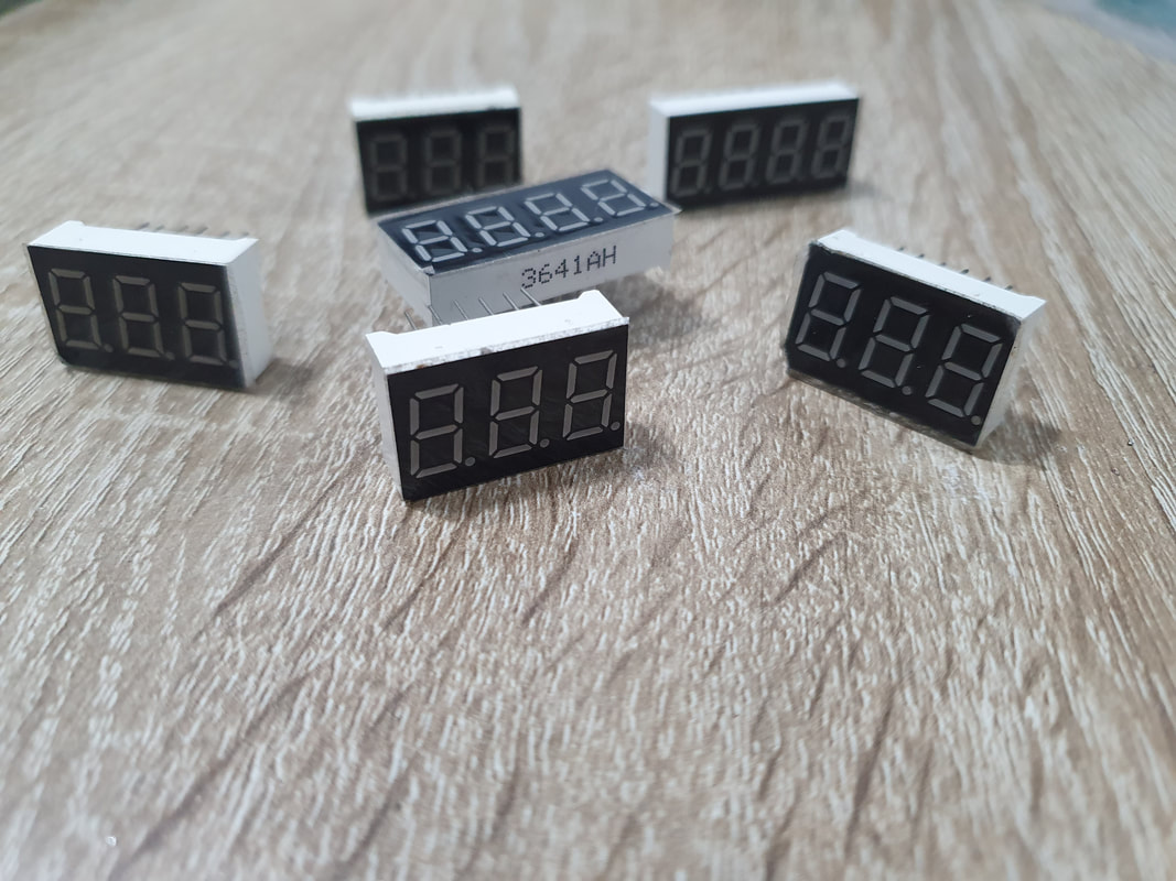
|
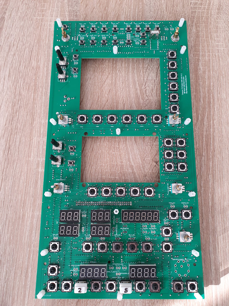
|
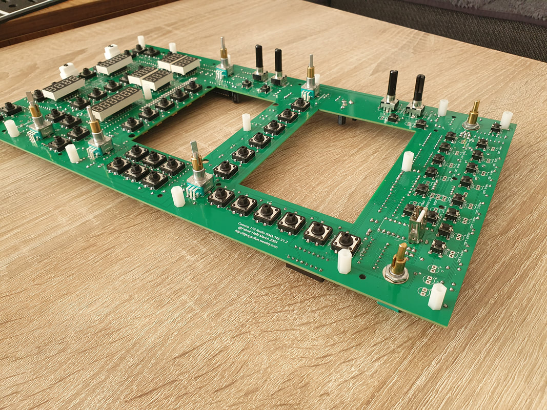
|
|
Next we solder the rotary switch which is streight forward. It fits only in 1 way because of the middle pin.
Once done, we connect the 5V power to the back of PCB, and also the usb cable to the Arduino.
We open flight simulator and choose Cessna 172.
We also open mobiflight.
Once mobiflight is open, we upload the configuration files which you will find in the Mobiflight config folder and run it. The radio should work as in the video demonstration below.
If it is not working, there are few things you need to check:
- You provide the board with 5V DC
- Your arduino is recognized by your PC and it is working correctly
- all shift registers are oriented correctly
- all electrolytic capacitors are oriented correctly
- there are no shortings on the back of the pcb, especially with those tiny pads. Go over the board with a magnifying glass or phone.
- you have no faulty shift registers or 7 segment displays.
- you have Common Cathode displays (Common Anode will not work)
I usually do this sequence:
Open flight simulator
Plug in 5V connector
Plug in the usb
Open mobiflight and run.
The video demonstration below shows the radio is working as expected and it is the same PCB that you will download when purchasing the radio.
Once done, we connect the 5V power to the back of PCB, and also the usb cable to the Arduino.
We open flight simulator and choose Cessna 172.
We also open mobiflight.
Once mobiflight is open, we upload the configuration files which you will find in the Mobiflight config folder and run it. The radio should work as in the video demonstration below.
If it is not working, there are few things you need to check:
- You provide the board with 5V DC
- Your arduino is recognized by your PC and it is working correctly
- all shift registers are oriented correctly
- all electrolytic capacitors are oriented correctly
- there are no shortings on the back of the pcb, especially with those tiny pads. Go over the board with a magnifying glass or phone.
- you have no faulty shift registers or 7 segment displays.
- you have Common Cathode displays (Common Anode will not work)
I usually do this sequence:
Open flight simulator
Plug in 5V connector
Plug in the usb
Open mobiflight and run.
The video demonstration below shows the radio is working as expected and it is the same PCB that you will download when purchasing the radio.
|
|
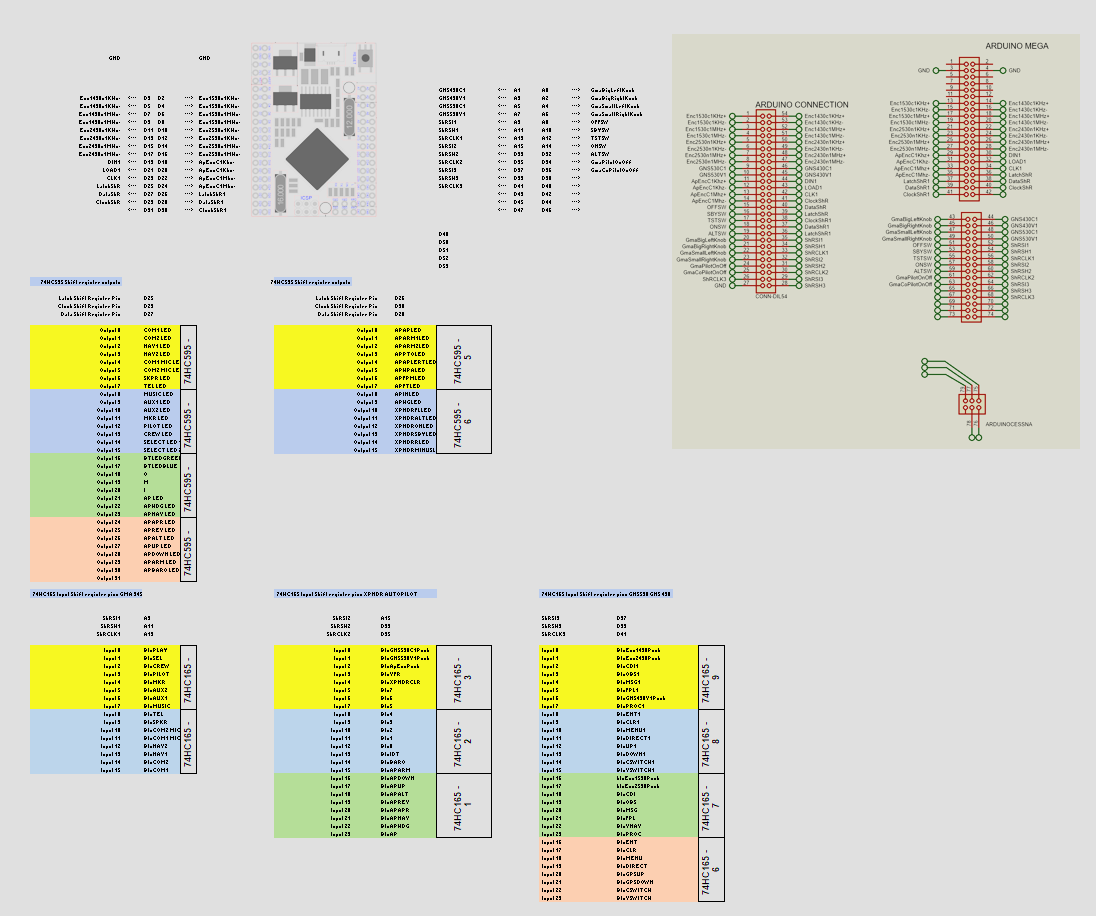
Pinouts
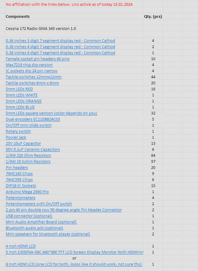
BOM
2015, Copyright AlbEAGLE