GPS
GPS V3.2.3
|
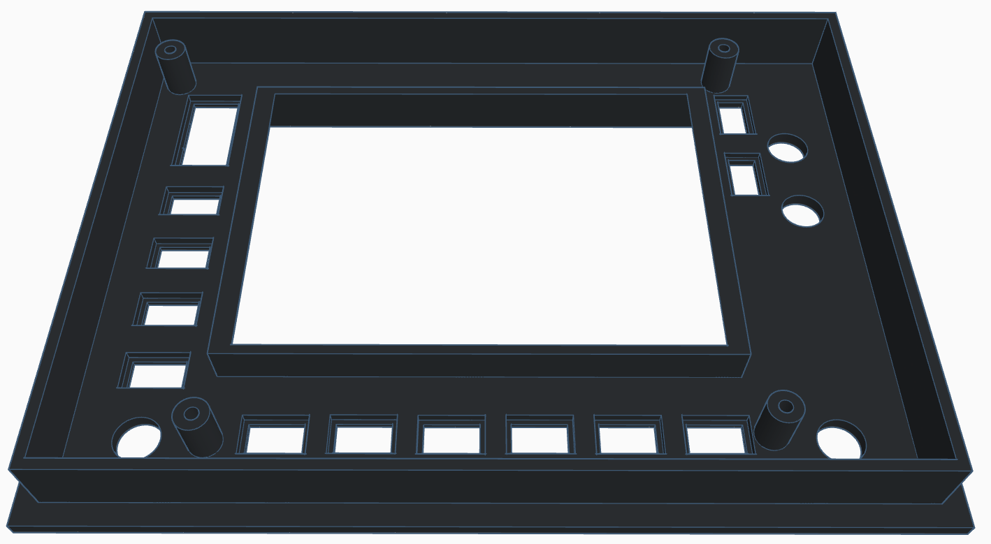
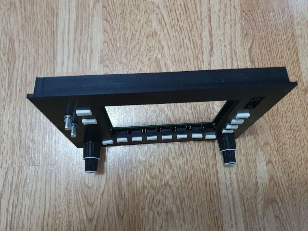
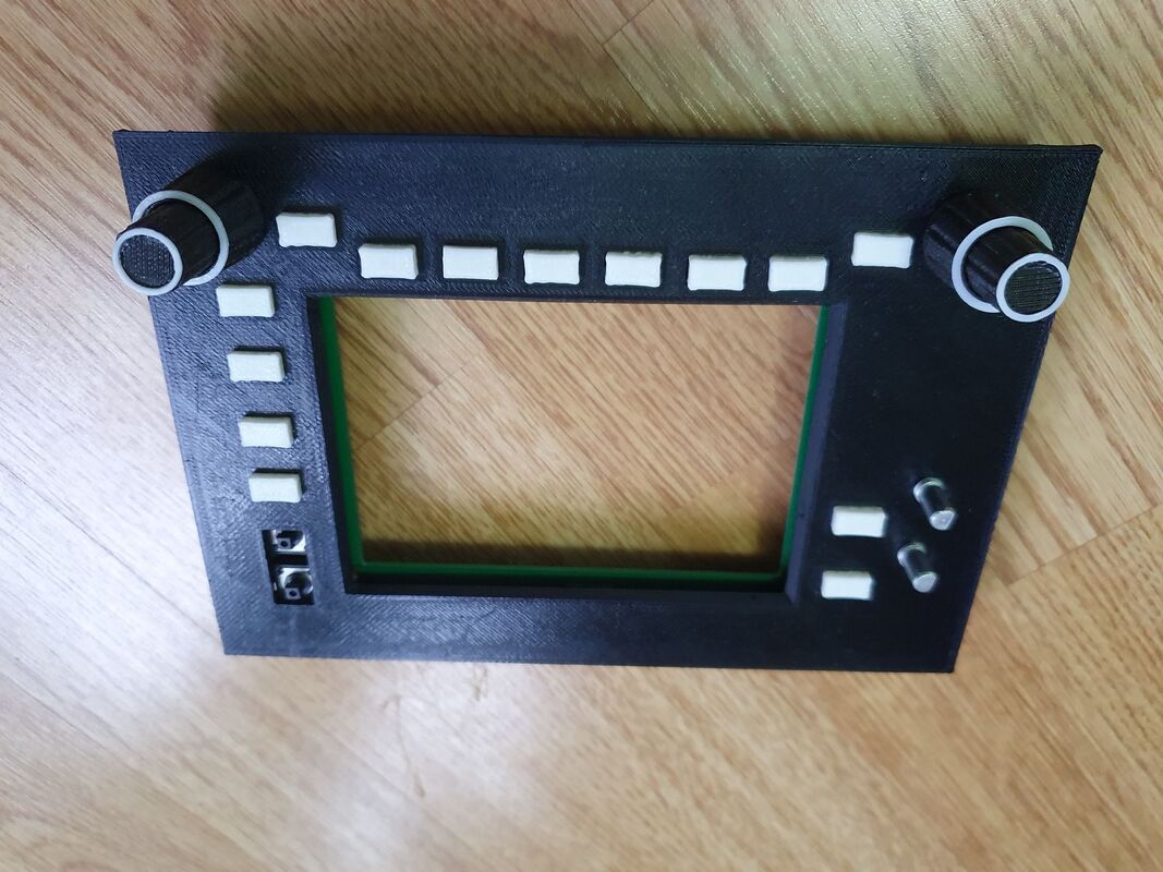
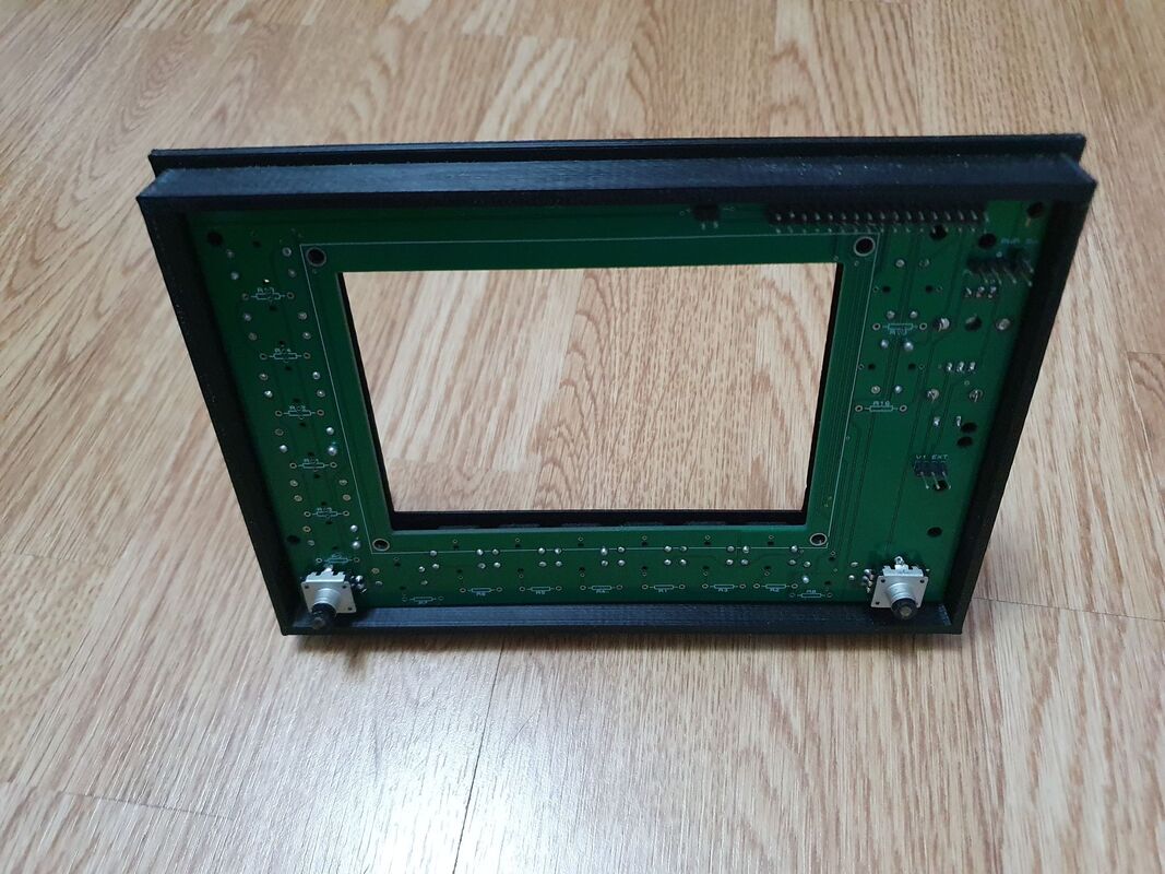
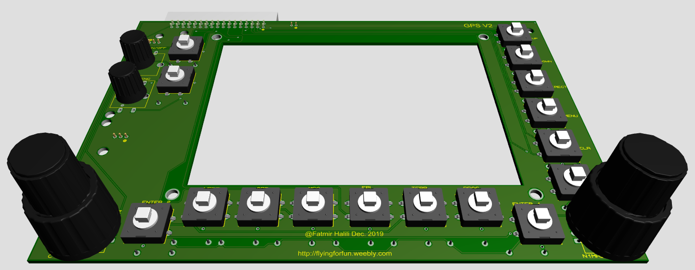
* Added holes to the pcb to assamble easier with the faceplate
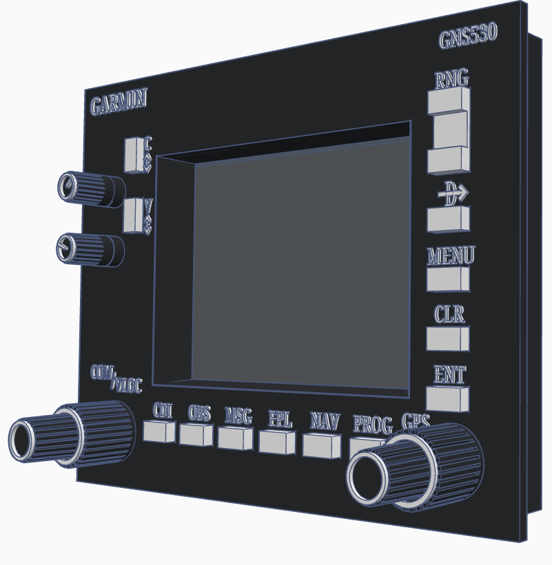
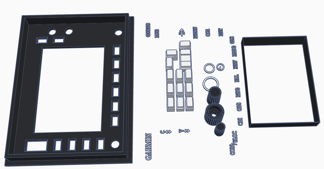
* Added spacers to the faceplate * Bezel will be printed together with the faceplate |
|
GPS V3.2.2
* Both potentiometers assigned to analog pins on Arduino
* Resistors R7 and R8 are both 10k (are labeled R7 and R8 instead of 10k)
* Resistors R7 and R8 are both 10k (are labeled R7 and R8 instead of 10k)
GPS V3.2.1
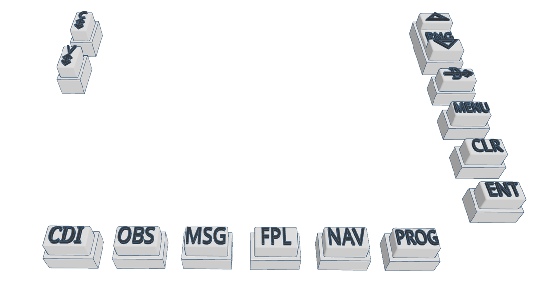
* Larger push button holes
GPS V3.2
* Fixed some issues with 74HC165 shift registers. Please check the forum for the fix of V3.1
* Replaced C1 and V1 Encoders with Potentiometers
* Replaced C1 and V1 Encoders with Potentiometers

| BOM_GPS_V3.2.xlsx |
|
|

|
| ||||
|
|
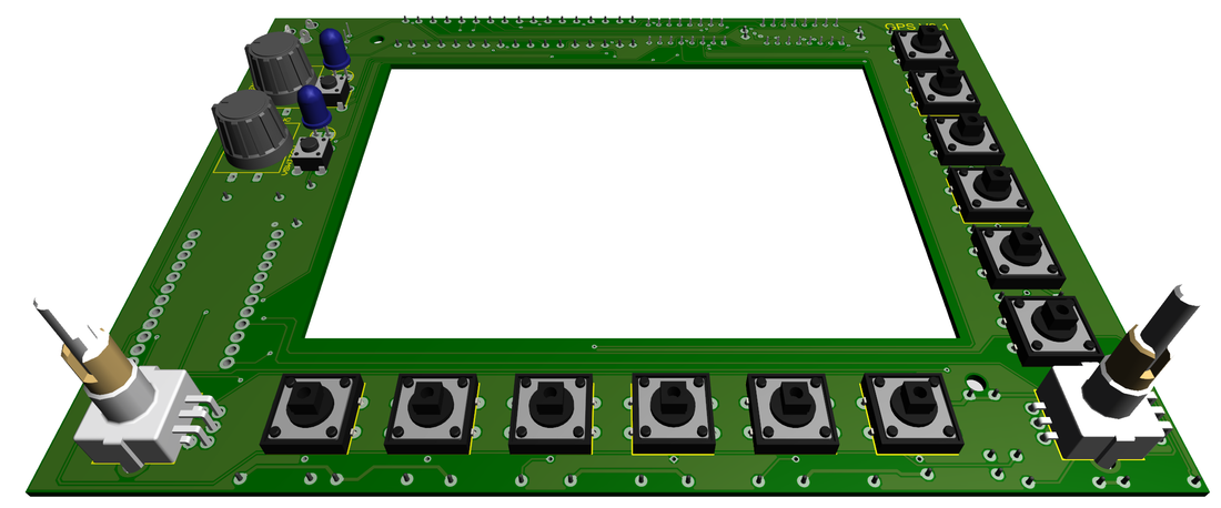
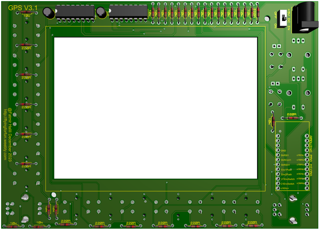
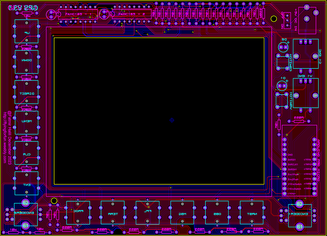
GPS V3.1
* Fixed the issue with the EC11EBB24C03 dual encoder connections
* Replaced Arduino Mega 2560 Pro with Arduino Pro Micro
* Added 2 x 74HC165 shift registers for the butttons
* Resized the PCB (made it smaller)
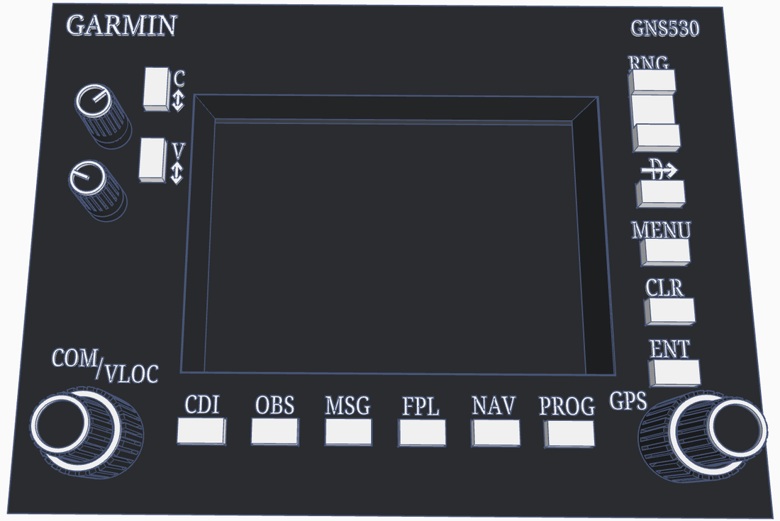
* Added holes to mount the screen and the faceplate
* Removed the external pins
* Replaced C and V 12mm switches with 6mm ones for space saving
* Replaced Arduino Mega 2560 Pro with Arduino Pro Micro
* Added 2 x 74HC165 shift registers for the butttons
* Resized the PCB (made it smaller)
* Added holes to mount the screen and the faceplate
* Removed the external pins
* Replaced C and V 12mm switches with 6mm ones for space saving
| BOM_GPS_V3.1.xlsx |
|
|
|
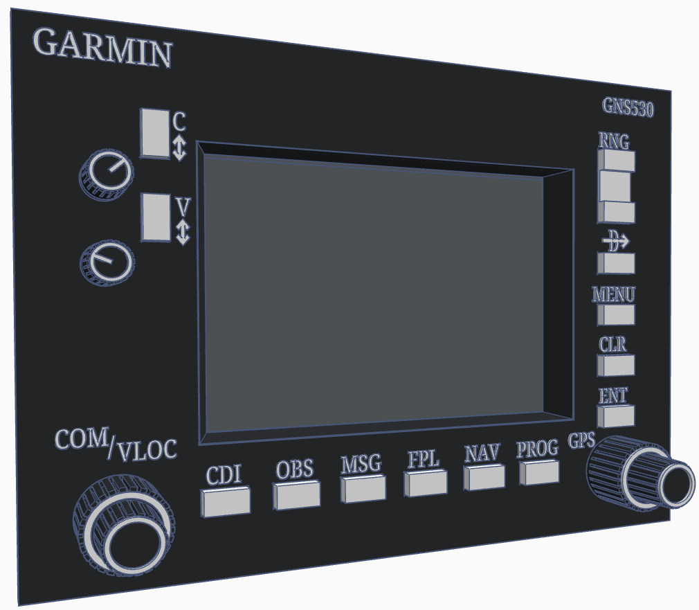
GPS V3.1 Faceplate
|
|
|
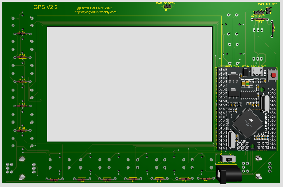
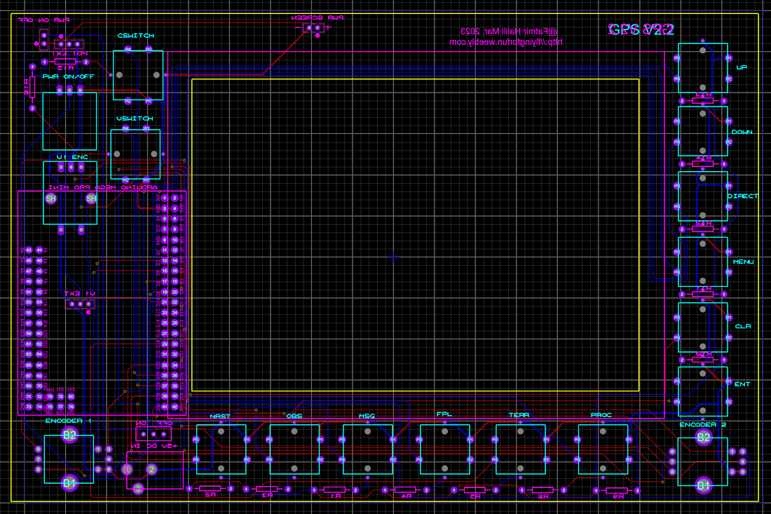
GPS V2.2 - has some issues in the dual encoder connections, those who have already purchased please just email me to get the new version V3.1
* Replaced DIY dual encoders with EC11EBB24C03
* Added Arduino Mega 2560 Pro at the back of the PCB to get rid of cables
* Added Arduino Mega 2560 Pro at the back of the PCB to get rid of cables
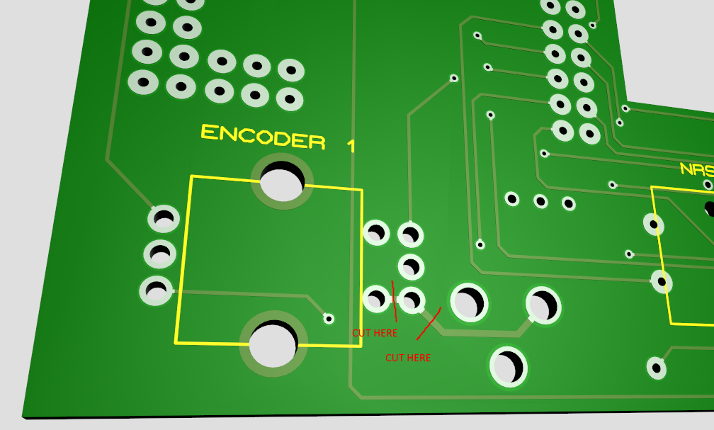
GPS V2.2 - workaround
|
Encoder 1 Front
|
Encoder 1 Back
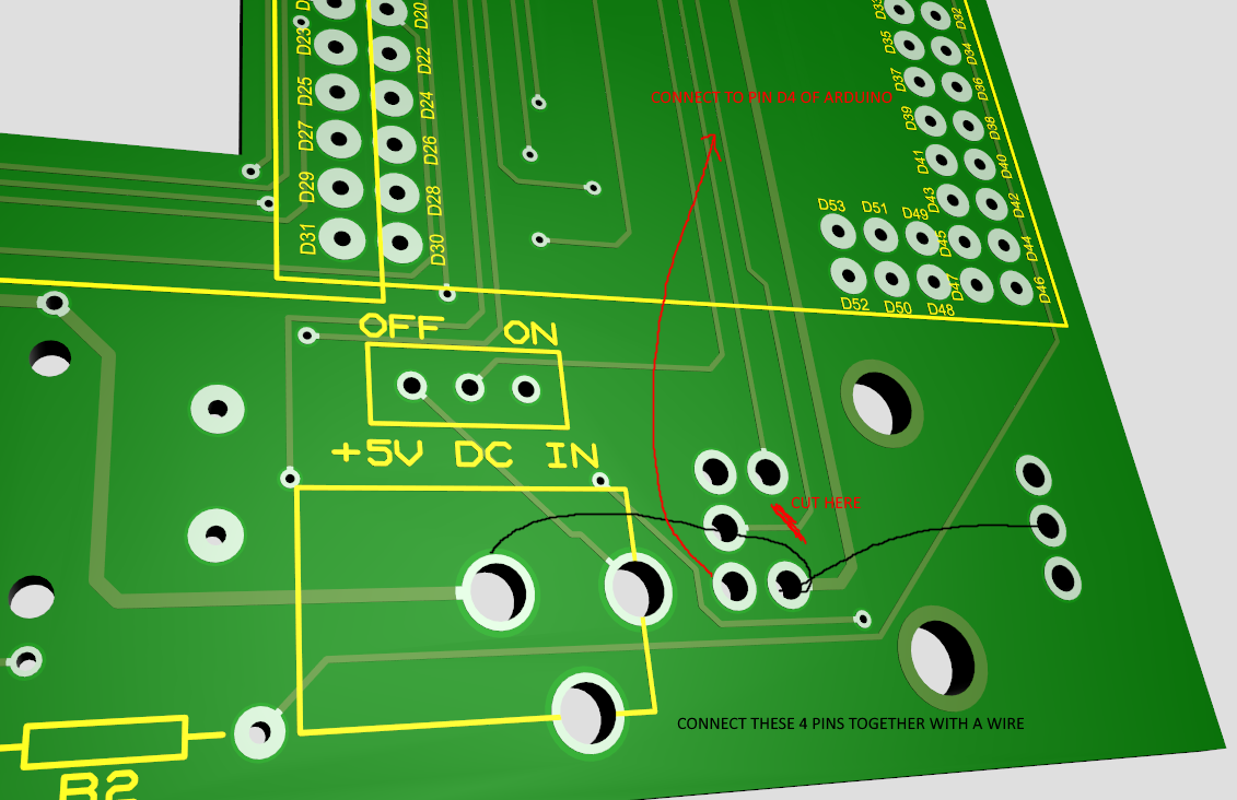
|
|
Encoder 2 Front
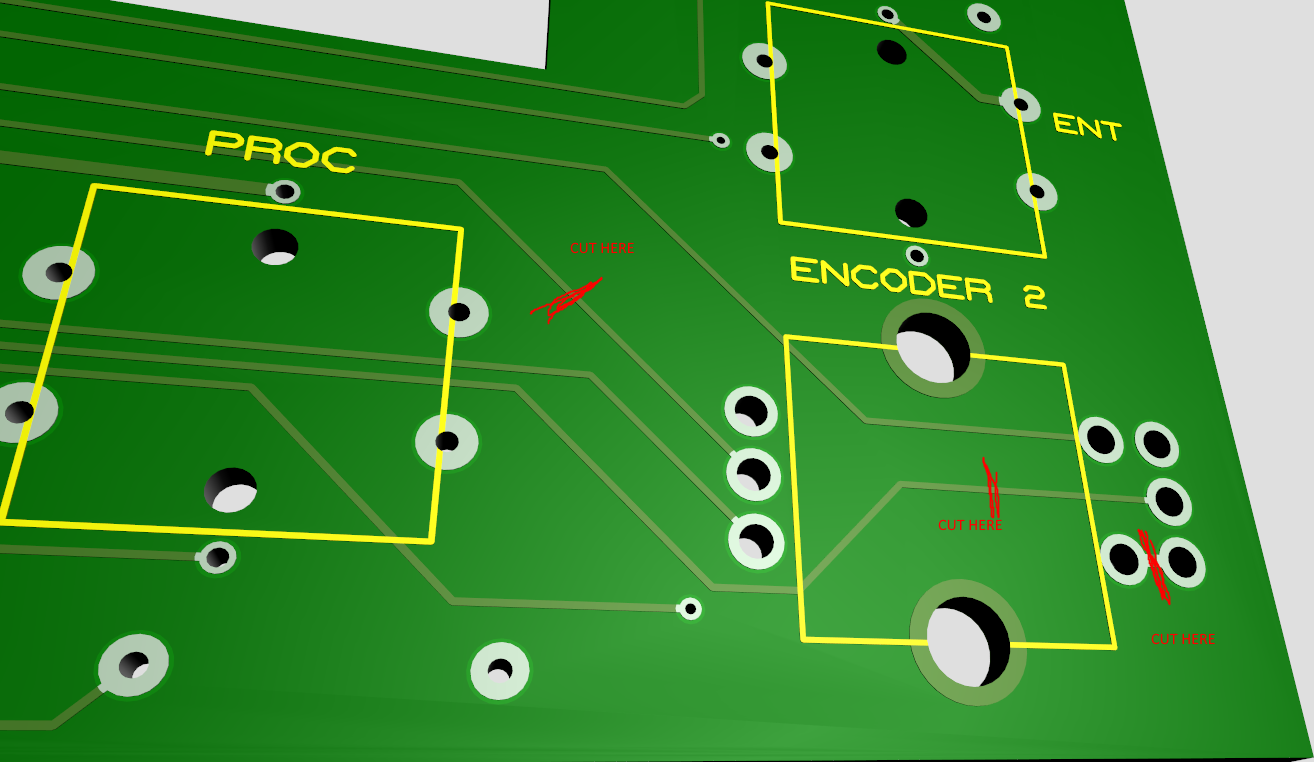
|
Encoder 2 Back
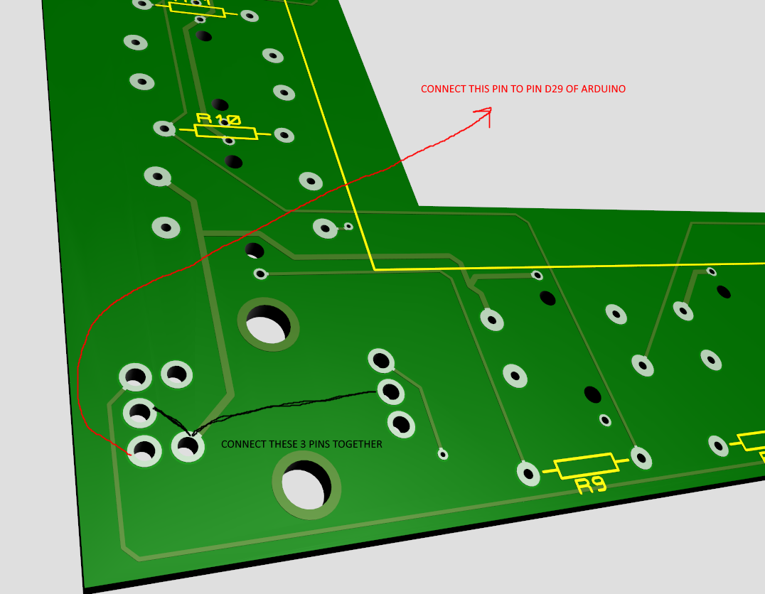
|
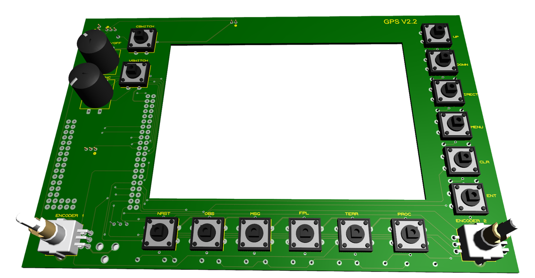
|
|
|
|
GPS V2.0
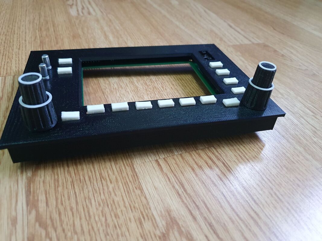
* Bigger holes for the Tactile button switches.
|
|
|
|
|
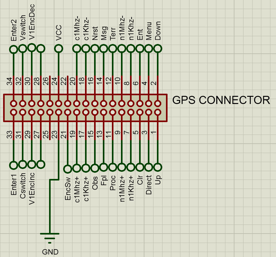
|
GPS PCB
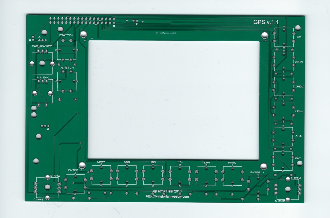
GPS V1.1 Components
Since the most expensive part of the radio stack and the GPS are the dual concentric encoders, my intentions were to make it cheap, so you need two encoders EC12 plastic encoders (EC12 link here) to mount on both sides of the PCB based on this principle:
Dual concentric encoders.
It is also designed to have tactile buttons with led's built in it like these ones:
Tactile buttons with leds.
but they need separate 12V power input so there is a little work to get it done, the other problem about the led tactile buttons is that it is hard to install the knob if you look at one of them. That's why this is optional as these normal tactile buttons have the same dimensions and were meant for it in the first place.
Normal Tactile buttons
Knobs need to be 3D Printed (I have already designed them) or you can use these ones for the bigger knobs
Big Knobs
and these ones for the smaller ones
Small nobs
As connector you can use this headers:
Headers
And the cables here:
Cable
For PWR ON/Off encoder I wanted to use this one with a different knob:
On/Off Encoder
And the V1 Enc is a normal Encoder.
If you use the buttons with leds, you need Resistors on the back (size needs to be calculated from you depending what tactile buttons you are going to use).
It was designed to be used with this screen:
LCD Screen
You have to be careful as there is another cheaper version of this display which can't be used as a monitor but is intended to be used only with raspberry pi (I made a mistake and purchased that version so I still have it unused, if anyone needs it for raspberry pi let me know, the price is like in internet ($30)).
2015, Copyright AlbEAGLE