Baron 58
(work in progress ...)
Content:
|
|
KNS 81
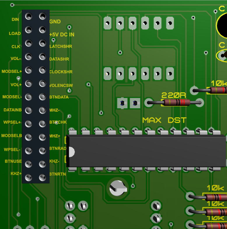
KNS 81 V1.1 fixed buttons connections
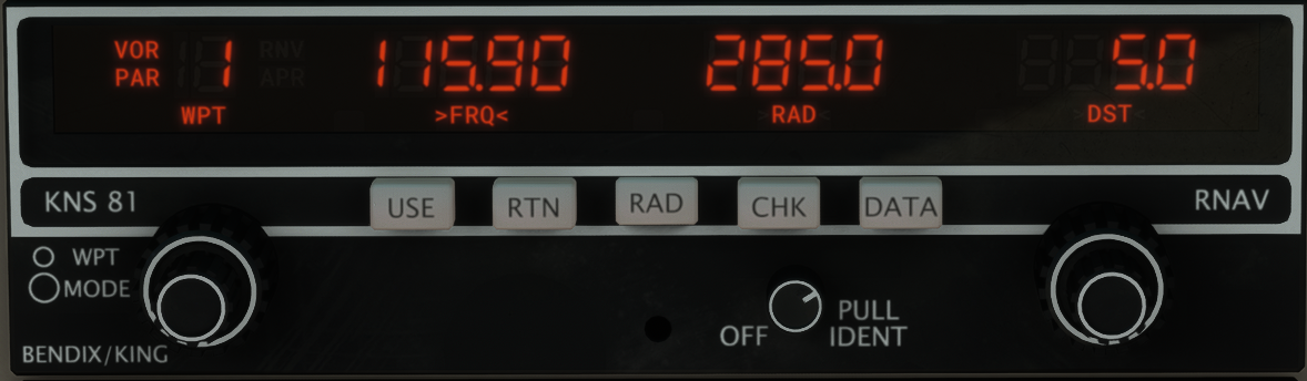
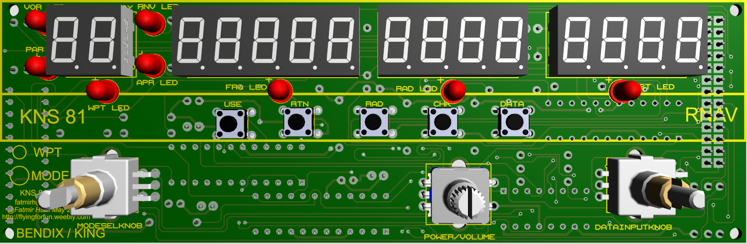
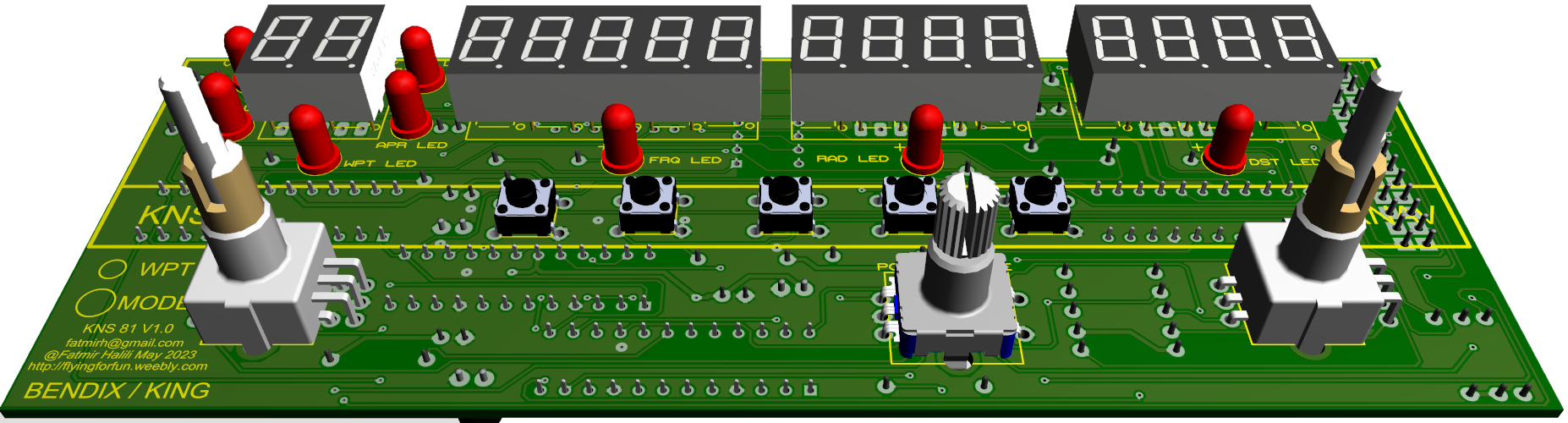
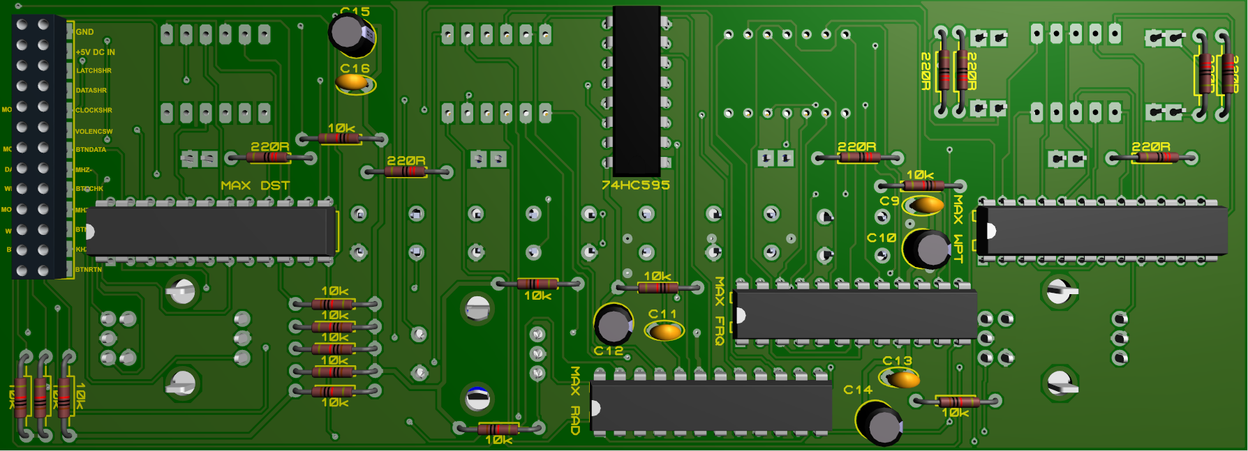
KNS 81 needs +5V DC external power supply to feed the displays and LEDs. The LEDs run through a 74HC595 shift register so that the arduino is safe from current draw.
KNS 81 needs +5V DC external power supply to feed the displays and LEDs. The LEDs run through a 74HC595 shift register so that the arduino is safe from current draw.
|
|
|
|
|
Components
|
To fully assemble the PCB, you will need the following components: 1 x 0.36 Inch 2 digit 7 segment display (CC) 2 x 0.36 Inch 4 digit 7 segment display (CC) 1 x 0.36 Inch 5 digit 7 segment display (CC) 4 x 100 nF ceramic capacitors 4 x 10uF electrolytic capacitors 1 x 74HC595 shift register 4 x Max7219 chips 8 x 5mm RED LED diodes 1 x EC11 rotary encoder with switch 2 x EC11EBB24C03 dual encoders 5 x 6mmx6mm micro switches 8 x 220R 1/4W resistors 14 x 10k 1/4W resistors Round hole headers for displays Male/Female header pins for outputs |
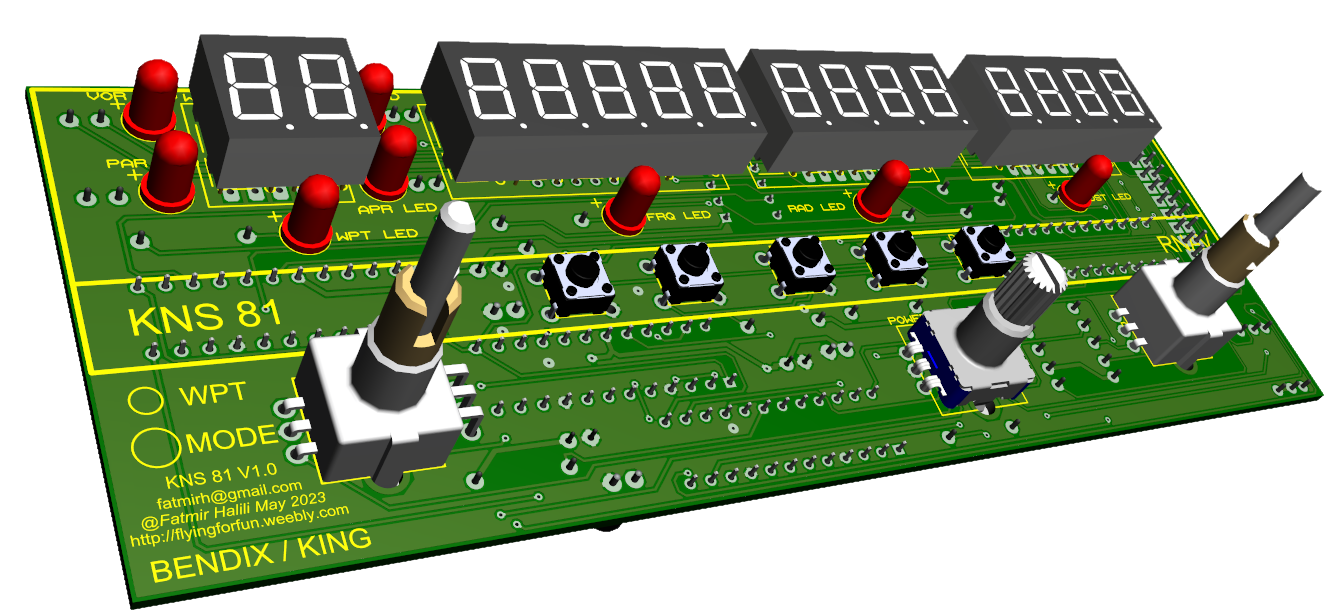
Shift register outputs:
WPT LED - Output 0 FRQ LED - Output 1 RAD LED - Output 2 DST LED - Output 3 VOR LED - Output 4 PAR LED - Output 5 RNV LED - Output 6 APR LED - Output 7 |
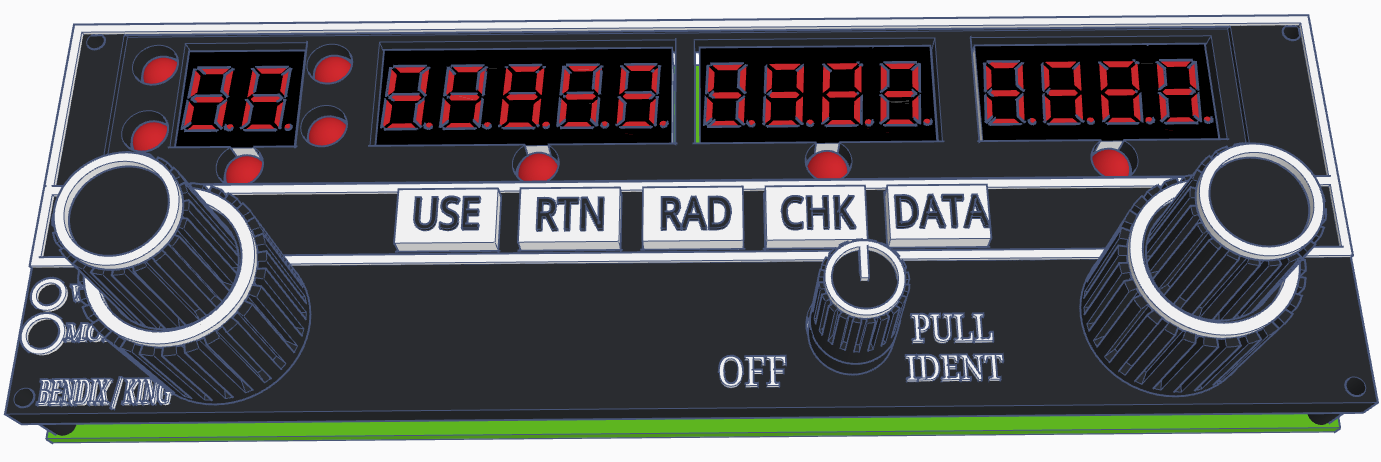
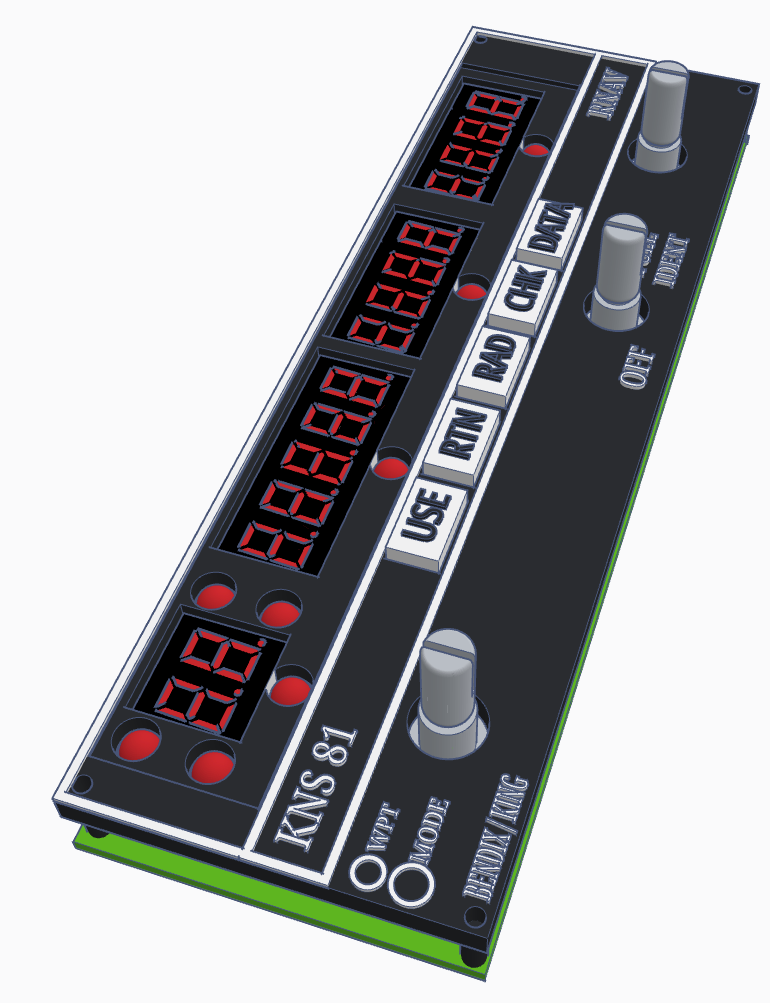
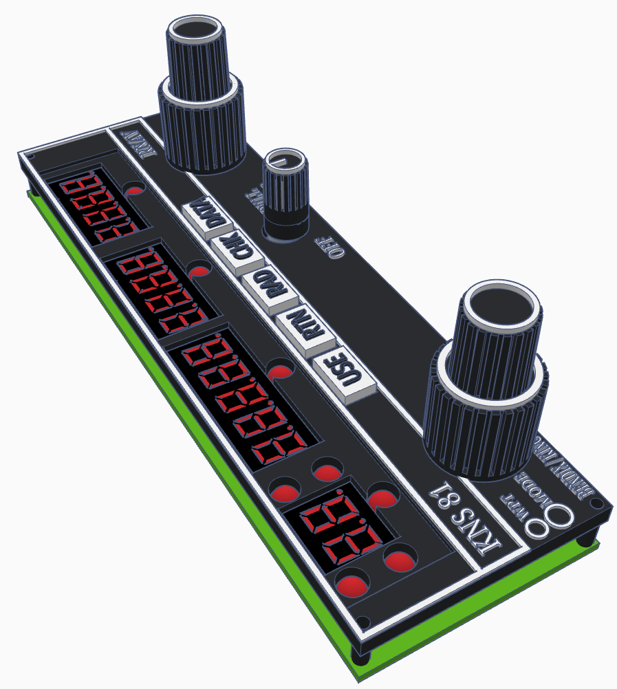
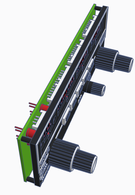
KNS 81 Faceplate
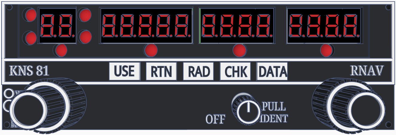
The best way would be laser engraving (or resin 3d printing) the faceplate, but since I am not familiar and don't own a laser myself neither do I own a resin 3D printer, I am designing the parts for normal 3d printing which is more difficult to achieve the desired look. Adding here also the different types of printers and printer settings.
The text should be printed with 0.2mm Nozzle.
The text should be printed with 0.2mm Nozzle.
|
|
|
|
|
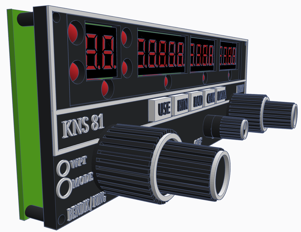
|
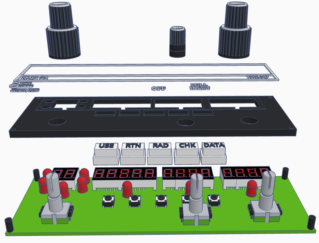
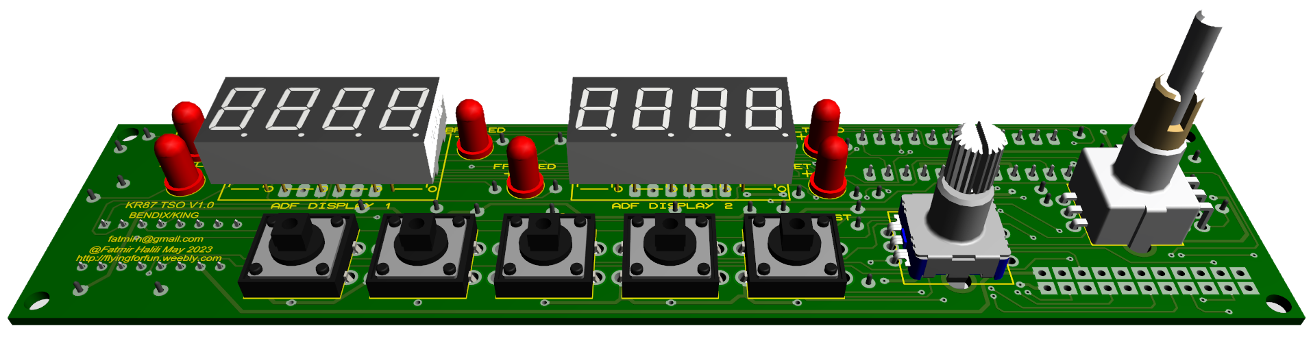
KR87-TSO
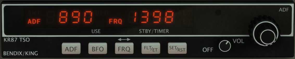
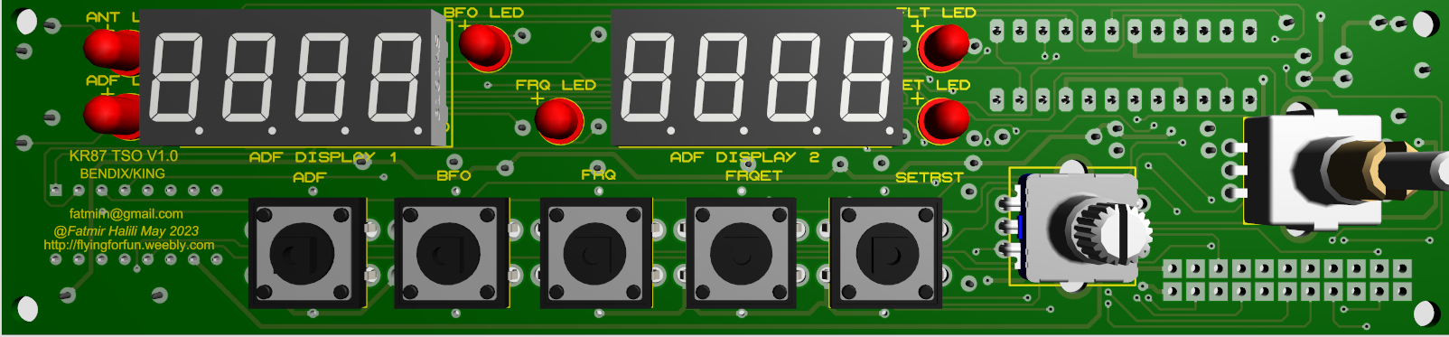
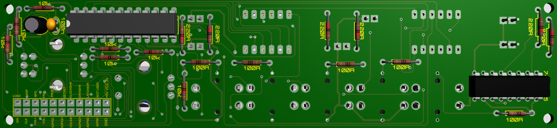
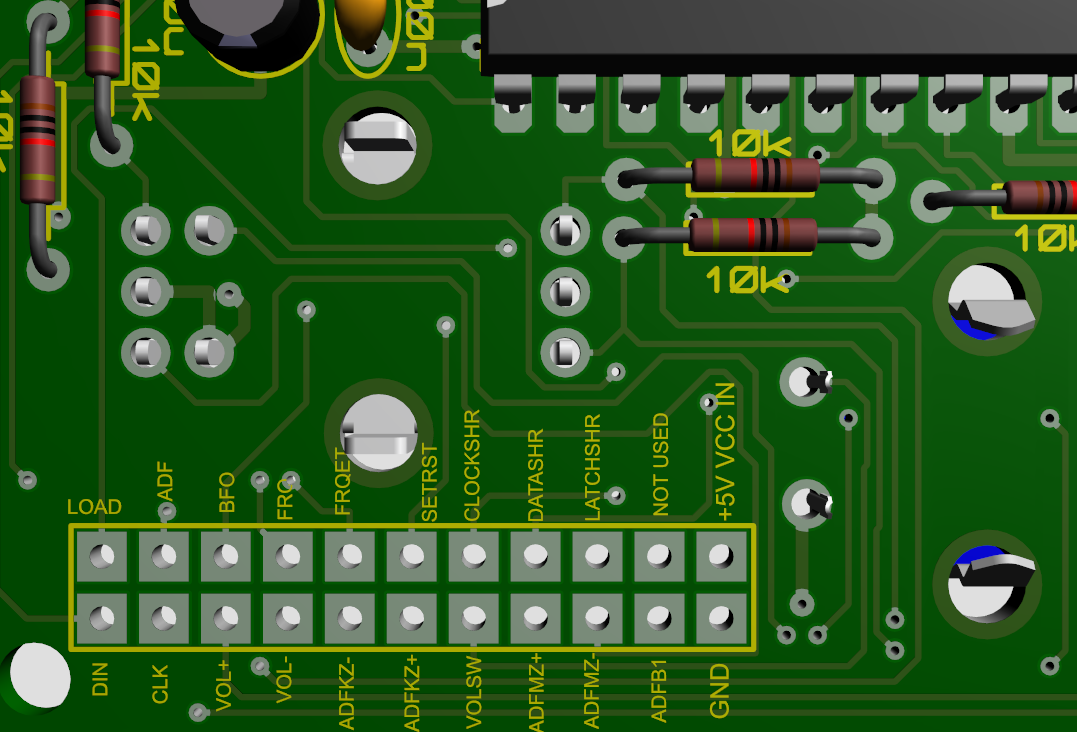
The KR87 also needs +5V DC external power supply to feed the displays and LEDs. The LEDs run through a 74HC595 shift register so that the Arduino is safe from current draw.
|
|
|
|
|
Components
|
To fully assemble the PCB, you will need the following components:
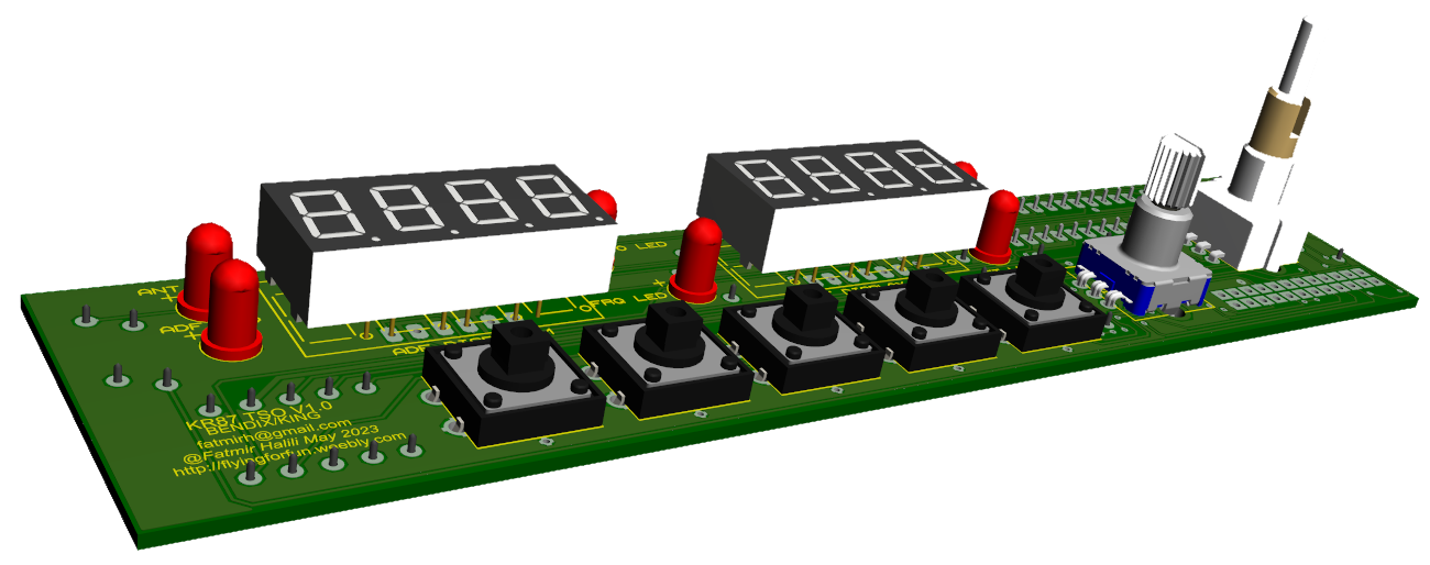
2 x 0.36 Inch 4 digit 7 segment display (CC) 1 x 100 nF ceramic capacitors 1 x 10uF electrolytic capacitors 1 x 74HC595 shift register 1 x Max7219 chips 6 x 5mm RED LED diodes 1 x EC11 rotary encoder with switch 1 x EC11EBB24C03 dual encoder 5 x 12mmx12mm tactile switches (with LEDs optional) 6 x 220R 1/4W resistors 5 x 100R 1/4W resistors 7 x 10k 1/4W resistors Round hole headers for displays Male/Female header pins for outputs |
Shift register outputs:
ANT LED - Output 0 BFO LED - Output 1 FRQ LED - Output 2 FLT LED - Output 3 ET LED - Output 4 ADF LED -Output 5 |
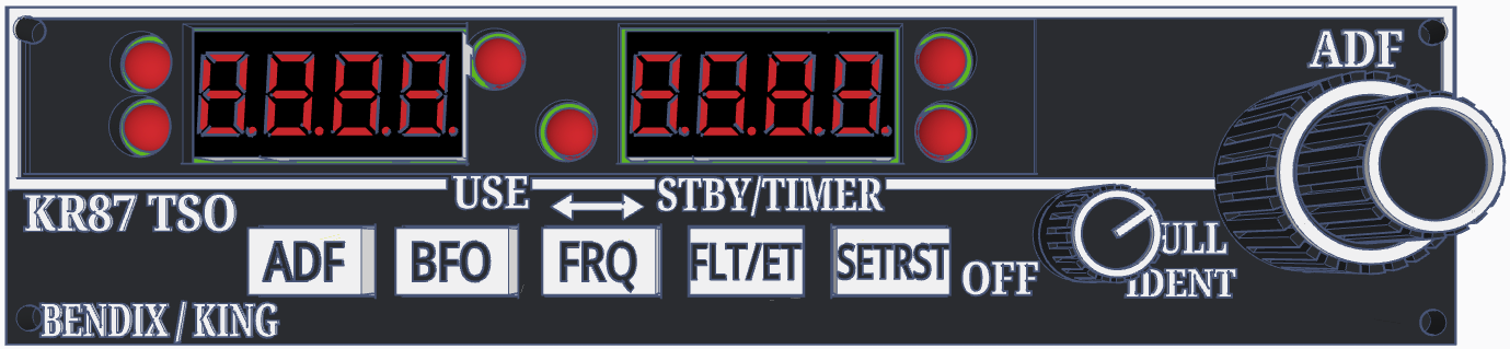
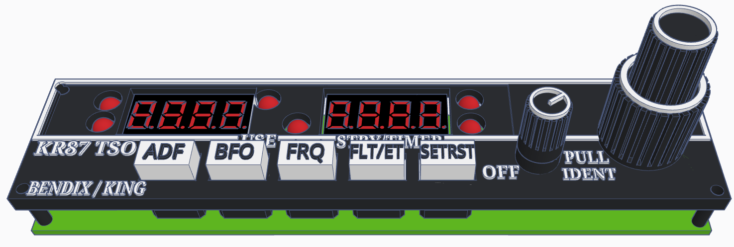
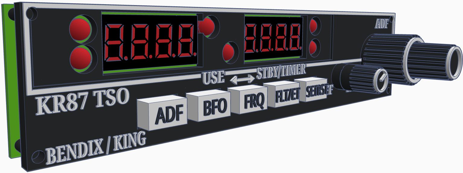
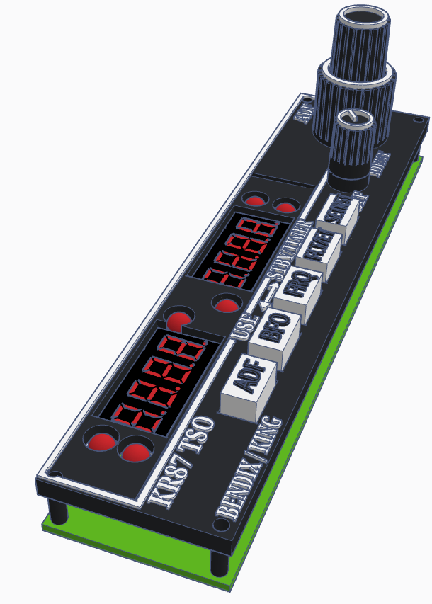
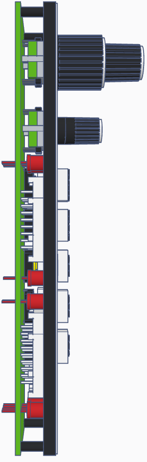
KR87 Faceplate
The best way would be laser engraving (or resin 3d printing) the faceplate, but since I am not familiar and don't own a laser myself neither do I own a resin 3D printer, I am designing the parts for normal 3d printing which is more difficult to achieve the desired look. Adding here also the different types of printers and printer settings.
The text should be printed with 0.2mm Nozzle.
The text should be printed with 0.2mm Nozzle.
|
|
|
|
|
KT70-TSO
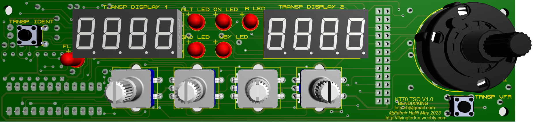
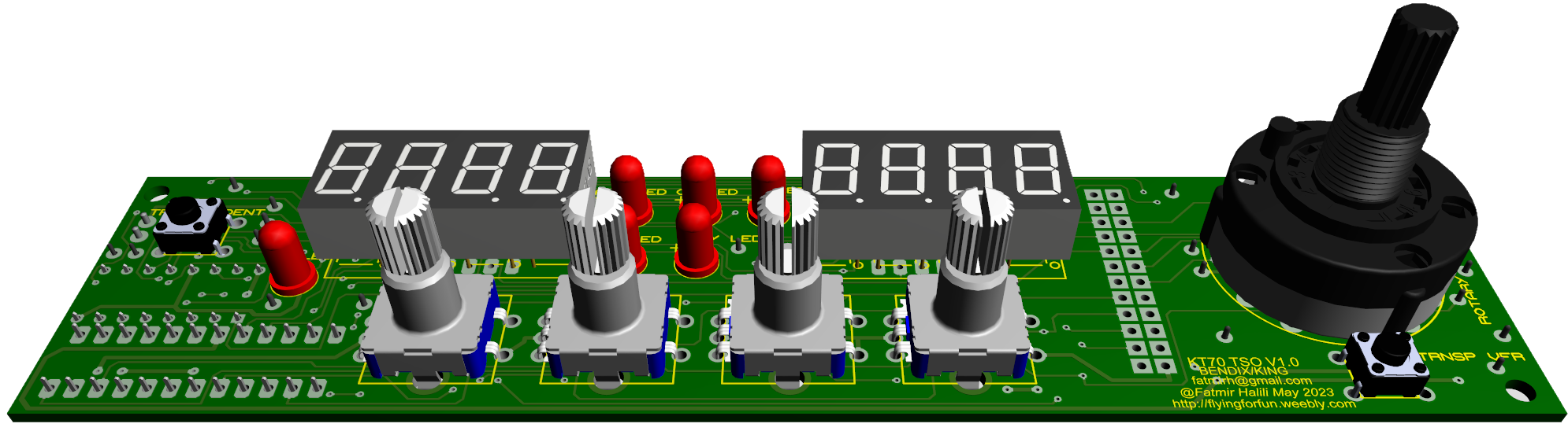
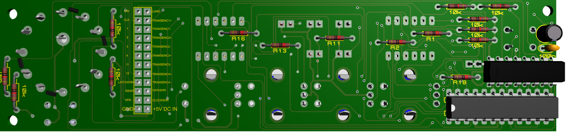
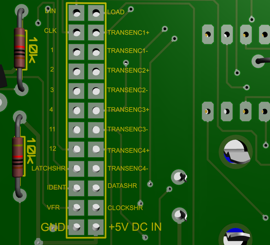
KT70 V1.1 - fixed buttons connections
Download instructions

| kt70_tso_v1.1_instructions.pdf |
|
|
|
|
|
Components
|
To fully assemble the PCB, you will need the following components:
2 x 0.36 Inch 4 digit 7 segment display (CC) 1 x 100 nF ceramic capacitors 1 x 10uF electrolytic capacitors 1 x Max7219 chips 1 x 74HC595 shift register 6 x 5mm RED LED diodes 4 X EC11 rotary encoders 2 x 6mmx6mm micro switches 9 x 10k 1/4W resistors Round hole headers for displays Male/Female header pins for outputs |
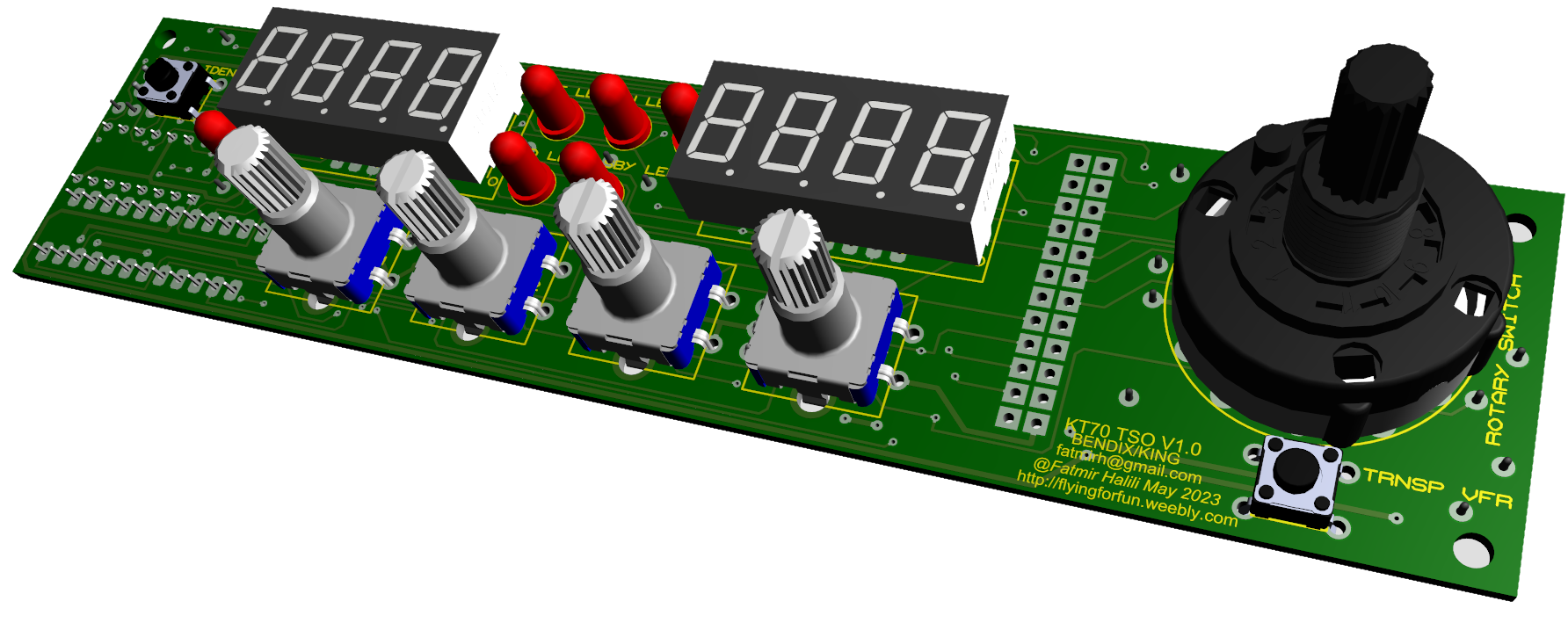
Shift register outputs:
FL LED - Output 0 ALT LED - Output 1 GND LED - Output 2 ON LED - Output 3 SBY LED - Output 4 R LED - Output 5 |
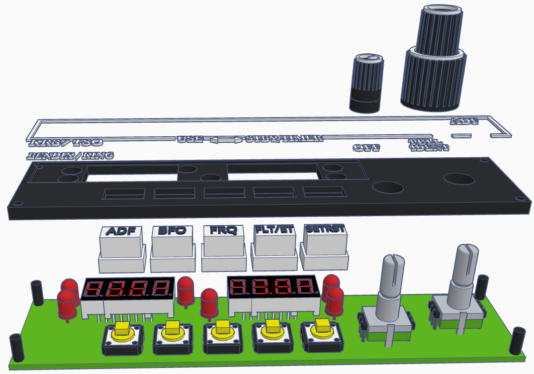
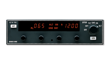
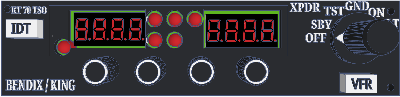
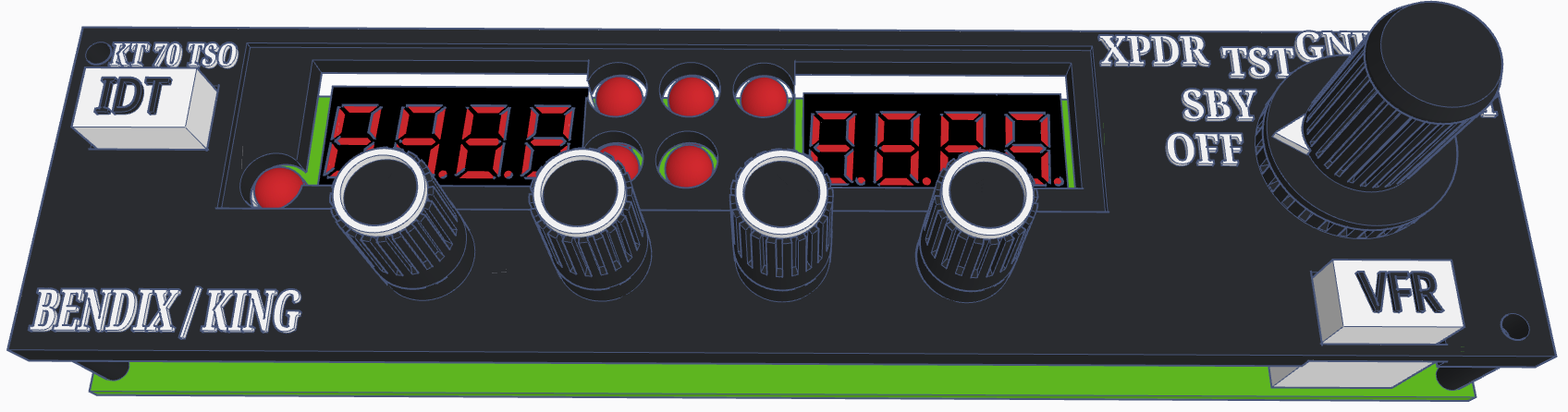
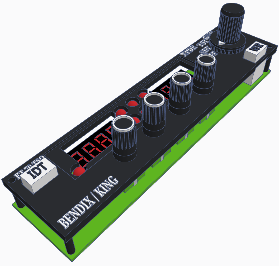
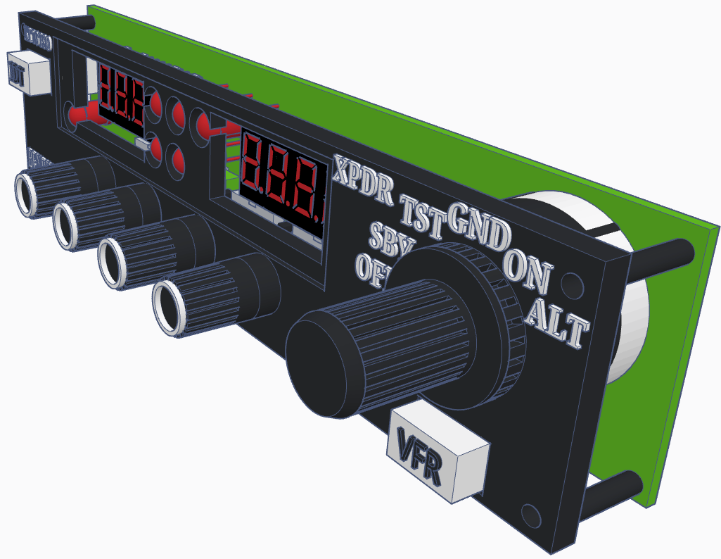
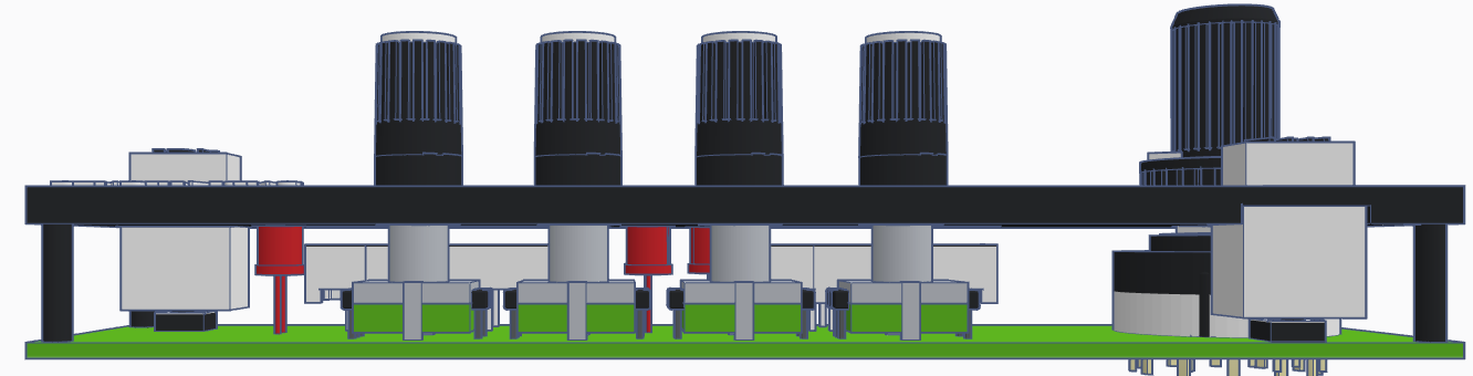
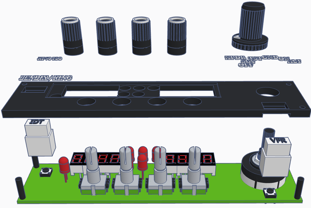
KT70 Faceplate
The best way would be laser engraving (or resin 3d printing) the faceplate, but since I am not familiar and don't own a laser myself neither do I own a resin 3D printer, I am designing the parts for normal 3d printing which is more difficult to achieve the desired look. Adding here also the different types of printers and printer settings.
The text should be printed with 0.2mm Nozzle.
The text should be printed with 0.2mm Nozzle.
|
|
|
|
|
KFC-150
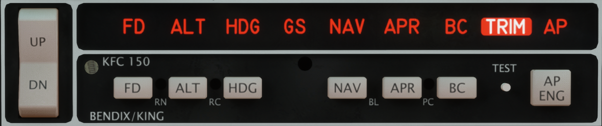
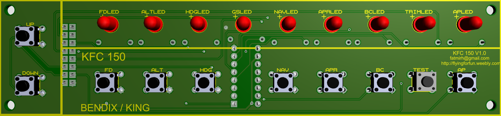
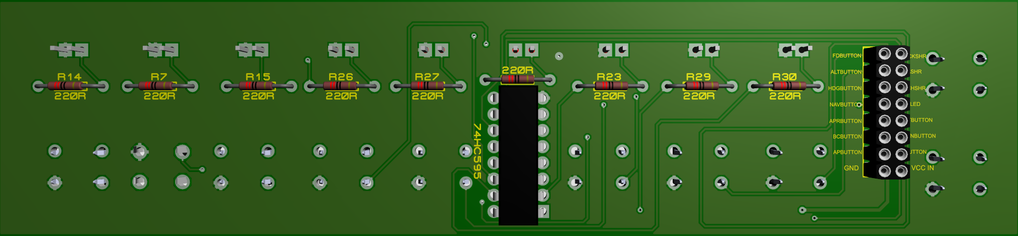
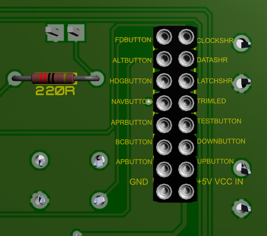
KFC 150 V1.1 - fixed buttons connections
The KFC 150 needs external +5V DC to run the LEDs through a 74HC595 shift register so that the Arduino is safe from current draw.
The KFC 150 needs external +5V DC to run the LEDs through a 74HC595 shift register so that the Arduino is safe from current draw.
|
|

|
|
|
Components
|
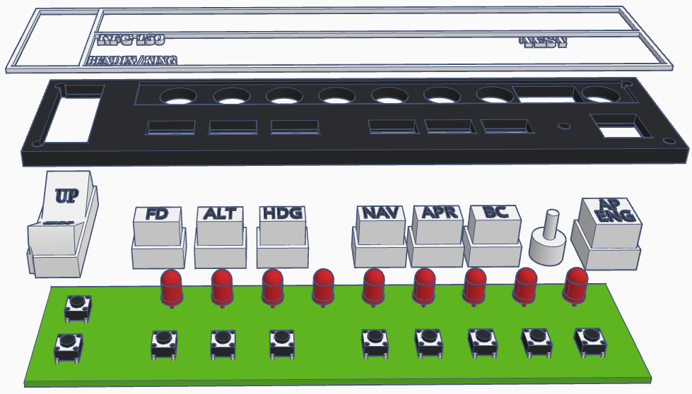
To fully assemble the PCB, you will need the following components: 9 x 5mm RED LED diodes 9 x 220R 1/4W resistors 1 x 74HC595 shift register 10 x 6mmx6mm micro switches 9 x 10k 1/4W resistors Male/Female header pins for outputs |
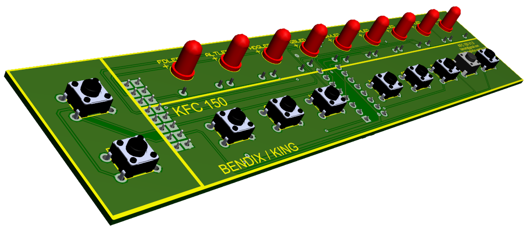
Shift register outputs:
FD LED - Output 0 ALT LED - Output 1 HDG LED - Output 2 GS LED - Output 3 NAV LED - Output 4 APR LED - Output 5 BC LED - Output 6 AP LED - Output 7 |
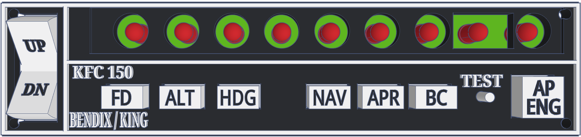
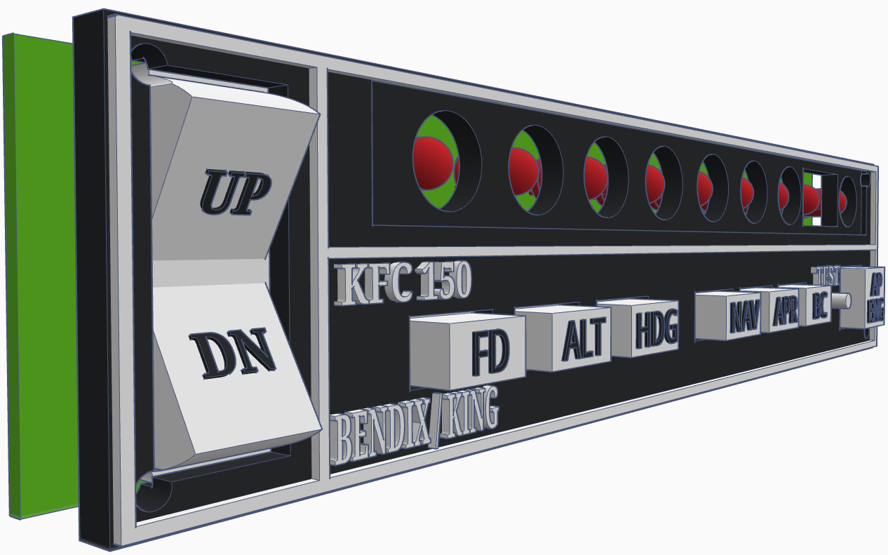
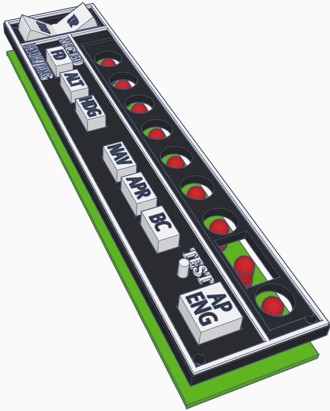
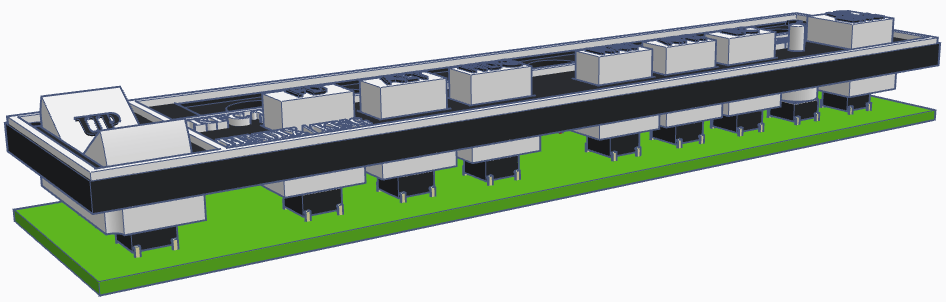
KFC 150 Faceplate
The best way would be laser engraving (or resin 3d printing) the faceplate, but since I am not familiar and don't own a laser myself neither do I own a resin 3D printer, I am designing the parts for normal 3d printing which is more difficult to achieve the desired look. Adding here also the different types of printers and printer settings.
The text should be printed with 0.2mm Nozzle.
The text should be printed with 0.2mm Nozzle.
|

|
|
|
|
2015, Copyright AlbEAGLE