FCU V1.6
(work in progress...)
Content:
|
|
Airbus A320 FCU PCB V1.6
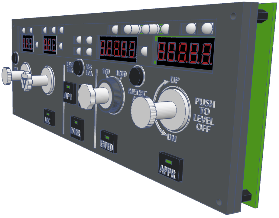
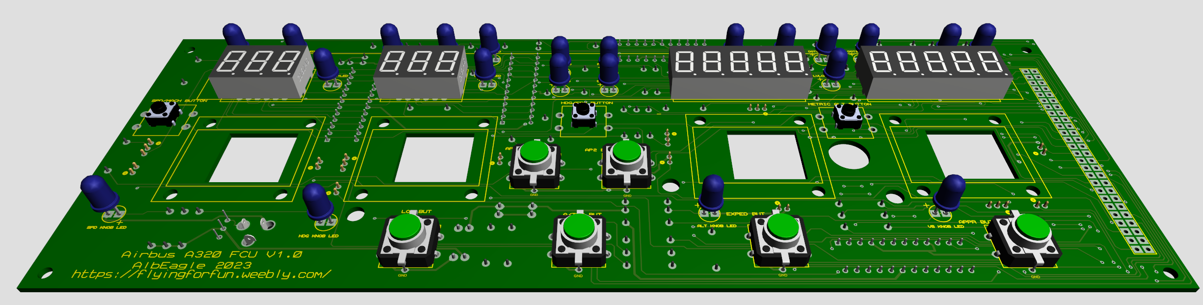
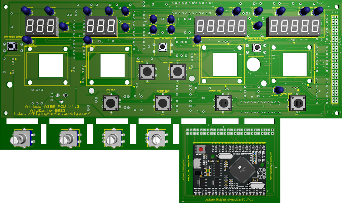
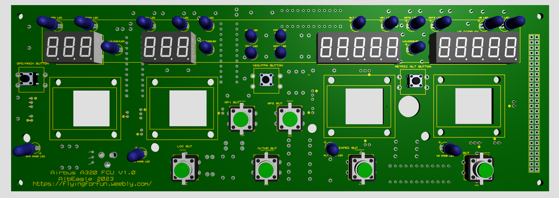
The Idea here is to build the FCU using the PCB to mount easily directly to the faceplate, without the need to build complex encoders mountings with push pull buttons. In this design, you will need a small pcb to mount the encoder which already has a push button. All you need to do is to 3d print a mount for the encoder to hold in place, which at the same time holds the pull switch. So the thickness should be about the same as the displays, which is great so we can mount the faceplate directly to the pcb. There is also an Arduino Mega Pro shield which you can easily just push into the slots on the pcb board. I am still working to finish the PCB, once finished, the files will be ready to for requests.
|
|
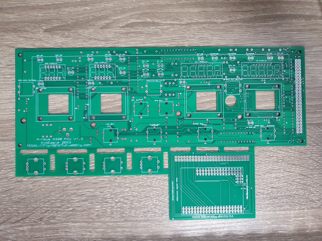
Front side of the FCU
|
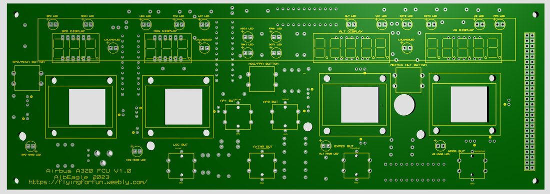
Front side of the FCU without elements
|
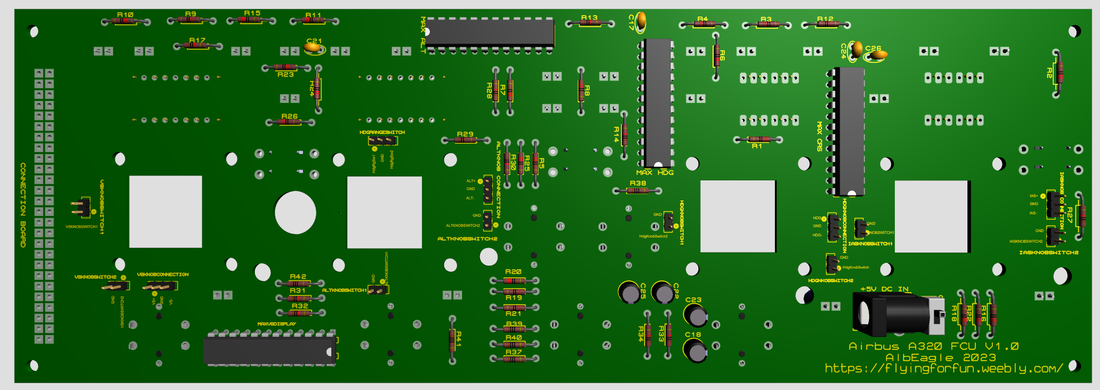
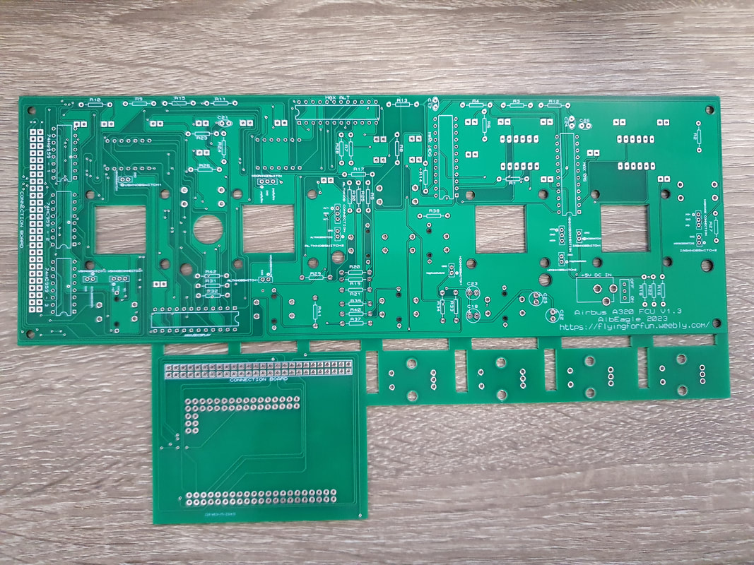
Back side of the FCU
|
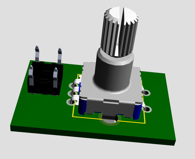
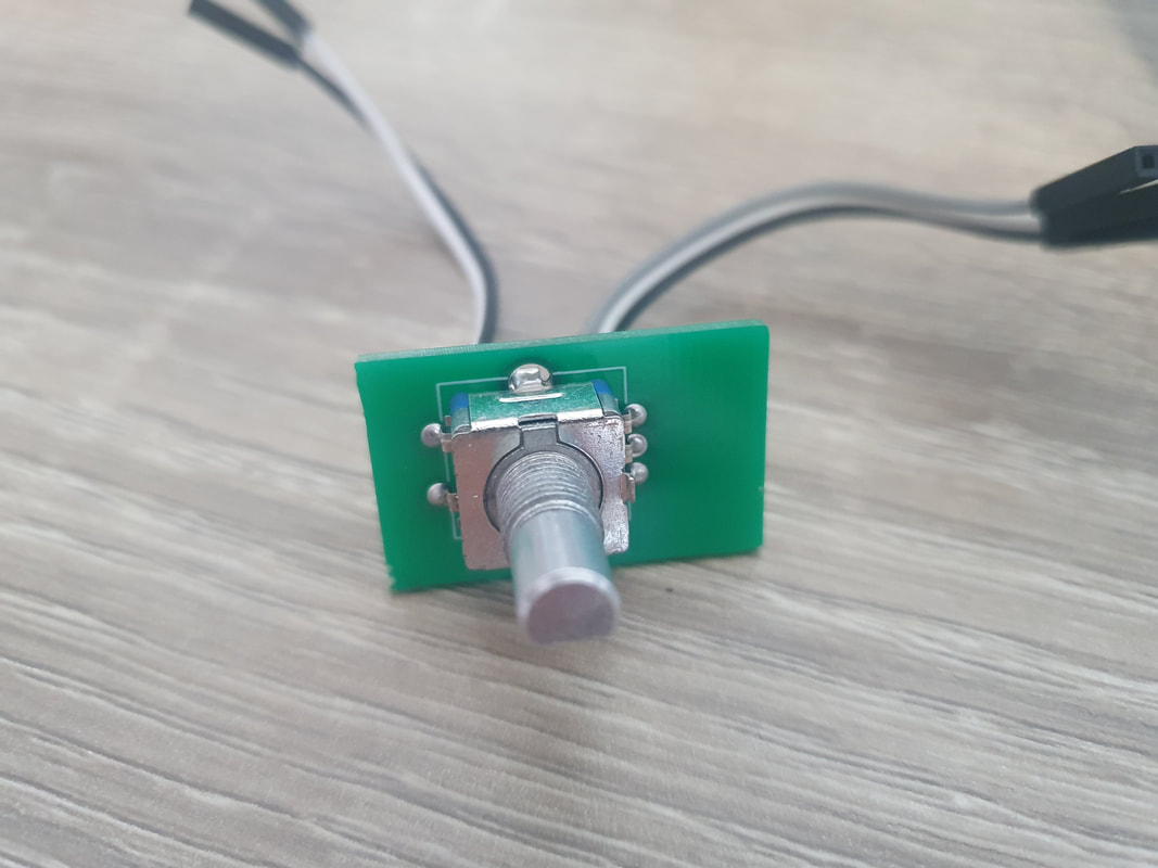
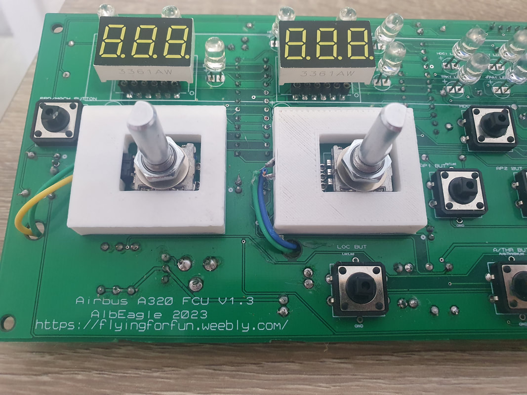
Mounted encoder
|
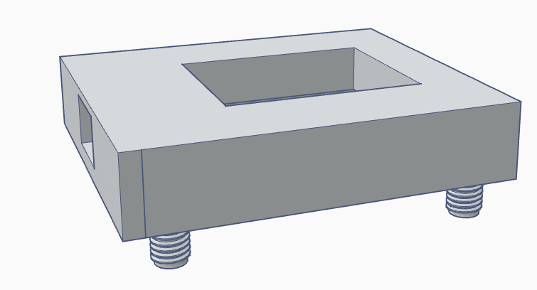
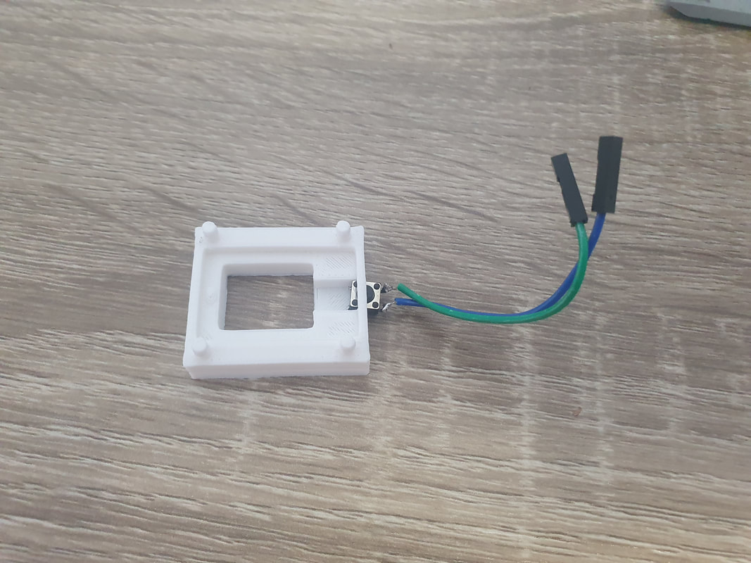
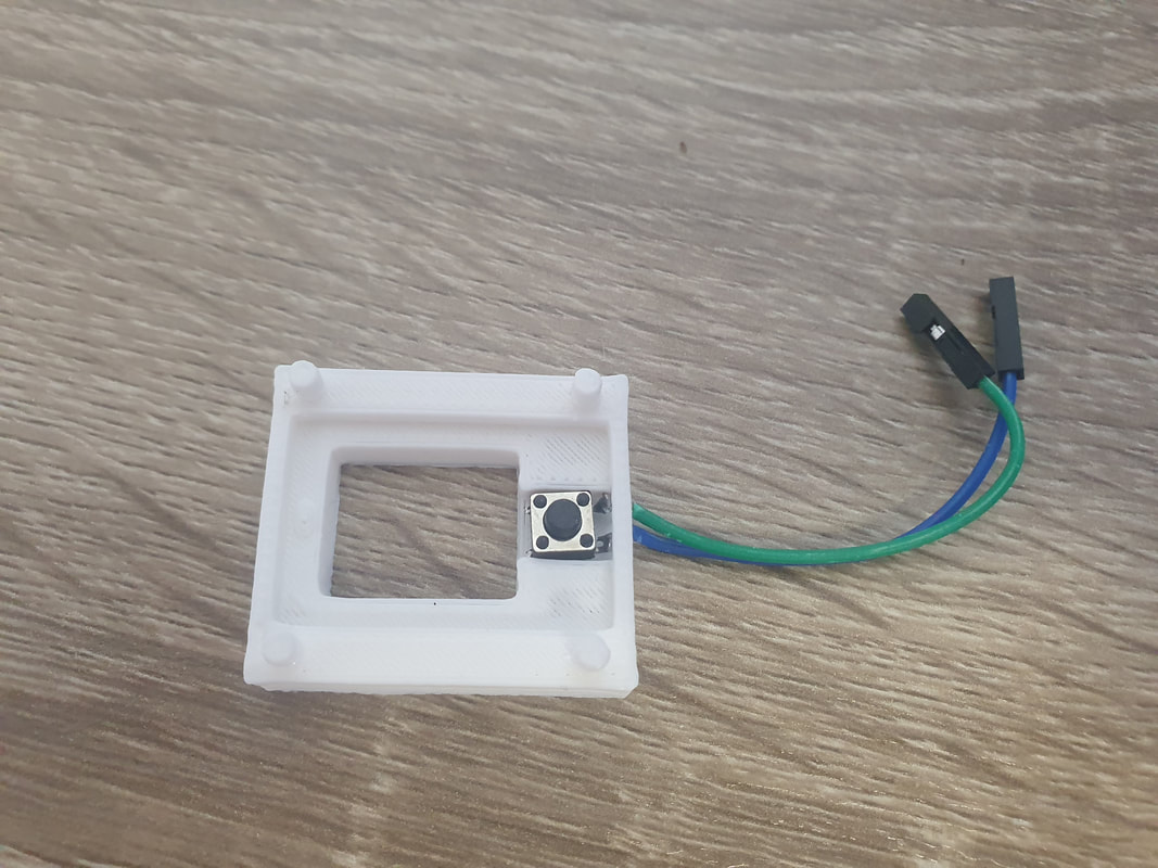
3D Printed mounting element for the encoders
|
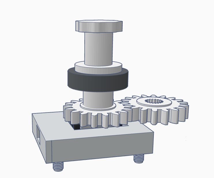
Encoder - switch mechanism
|
Components
|
To fully assemble the PCB, you will need the following components:
1 pcs Arduino Mega 2560 Pro --------------------------------------------- 35 pcs 220 Ohm 1/4W resistors ------------------------------------------- 12 pcs 10k 1/4W resistors ------------------------------------------------- 4 pcs 100 nF ceramic capacitors ------------------------------------------ 4 pcs 10uF electrolytic capacitors ----------------------------------------- 3 pcs 74HC595 shift registers --------------------------------------------- 4 pcs Max7219 chips ------------------------------------------------------ 27 pcs 5mm white LED diodes --------------------------------------------- 6 pcs 2x5x7mm square green LED diodes ---------------------------------- 9 pcs 12mmx12mm tactile buttons ---------------------------------------- 2 pcs 0.36 inch 3 digit 7 segment displays (white) - common cathode ------ 2 pcs 0.36 inch 5 digit 7 segment displays (white) - common cathode ------ 4 pcs EC11 rotary encoders with switch (preferably 20mm to 25mm long) -- 1 pcs DC Input Jack ------------------------------------------------------- 1 pcs rotary switch ------------------------------------------------------- 4 pcs 9mm spacers ------------------------------------------------------- 2 pcs round female header pins for 7 segment displays (optional) ---------- 4 pcs 24 pin narrow dip sockets for max7219 chips (optional) --------------- 2 pcs 40 pin double row 90 degree angle Pin Header Connector ------------ 3 pcs 16 pin dip sockets for shift registers (optional) ----------------------- 4 pcs single row male/female 40 pin headers ----------------------------- 4 pcs 6mmx6mmx5mm micro switches ---------------------------------- I don't have any affiliation with the above links, they are just links where i purchased my parts. These prices are as of today (06.05.2023) and they are calculated with shipping to my country (prices for shipping to your country might be different). Also pcb shipping are not included as it varies from country to country. With this amount of components, you will have a lot of spares for other projects as well. If you add here the 10 Euro for gerber files and 17.50 Euro for 5 pcs PCB production by JLCPCB (without shipping which depends on your country), you will have another 27.5 Euro, so the total would be around 69 Euro. For the faceplate you will either need to 3D print it or cut using a CNC machine. For the buttons, encoder mounters and knobs you will also need a 3d printer |
1 pcs 7.17 Euro 100 pcs 0.45 Euro 100 pcs 1 Euro 100 pcs 1 Euro 50 pcs 1.5 Euro 10 pcs 1.2 Euro 10 pcs 1.8 Euro 100 pcs 1.5 Euro 100 pcs 1.6 Euro 30 pcs 1.4 Euro 3 pcs 0.9 Euro 3 pcs 2.7 Euro + shipping 3 Euro 5 pcs 2.5 Euro 10 pcs 0.9 Euro 3 pcs 2 Euro 50 pcs 1.4 Euro 10 pcs 2 Euro 10 pcs 1.3 Euro 2 pcs 1.8 Euro 50 pcs 1 Euro 10 pairs 2.3 Euro Components 41.5 Euro Gerber 10 Euro PCB (5pcs) 17.5 Euro Total 69 Euro (PCB shipping exluded) |
|
Assembly
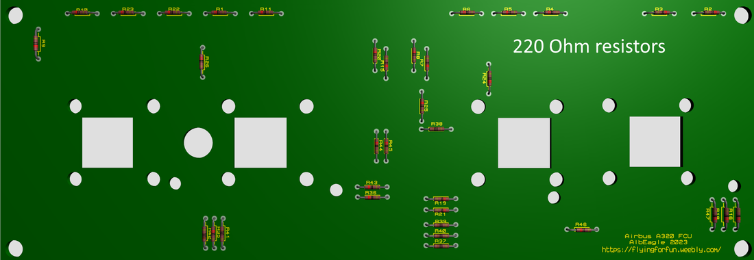
First thing you need to do is to cut off the Arduino Shield and 4 small encoder plates from the main PCB. After you are done, you can start with soldering the components to the PCB. Of course there is no particular way of soldering them and you can solder them in the order you find the easiest. I would suggest to start soldering the 220 Ohm and 10 k resistors first.
|
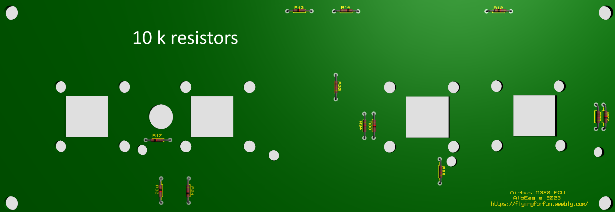
|
Than you continue with the 24 pin dip sockets for the MAX7219 chips, 16 pin dip sockets for the 74HC595 shift registers and the capacitors. The IC sockets for MAX chips and shift registers are optional, but I recommend to use them, which will save you a lot of trouble in case you have a faulty component or it gets burned during the usage.
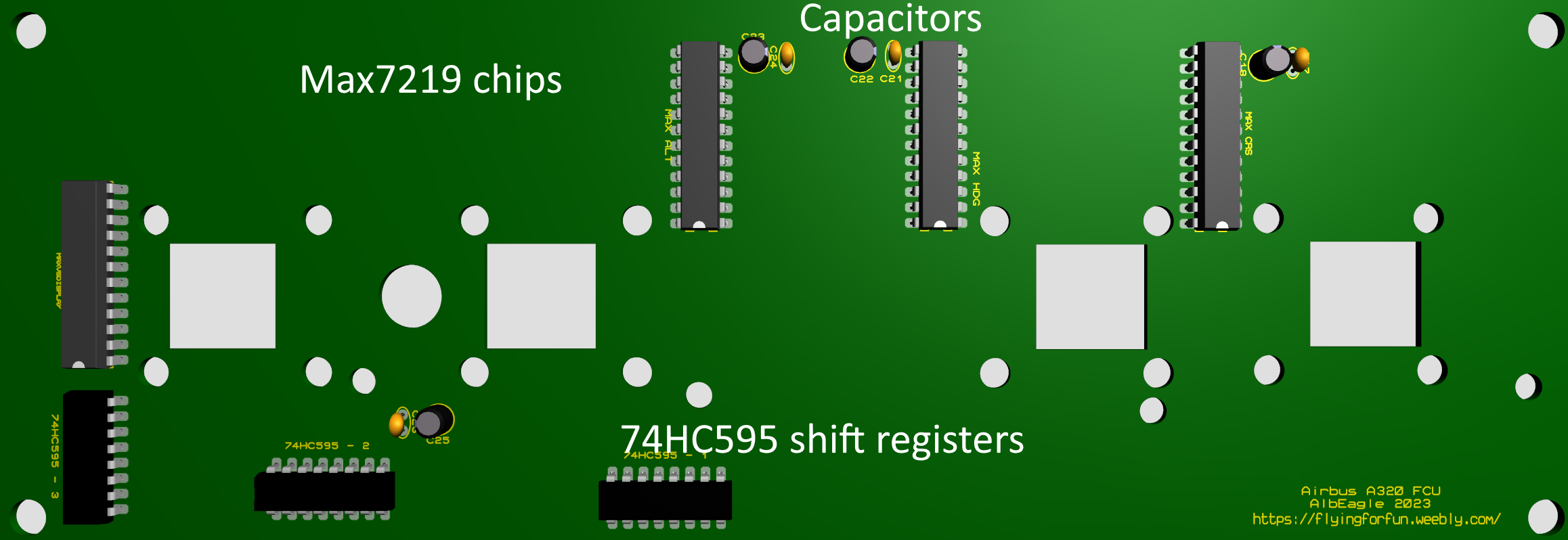
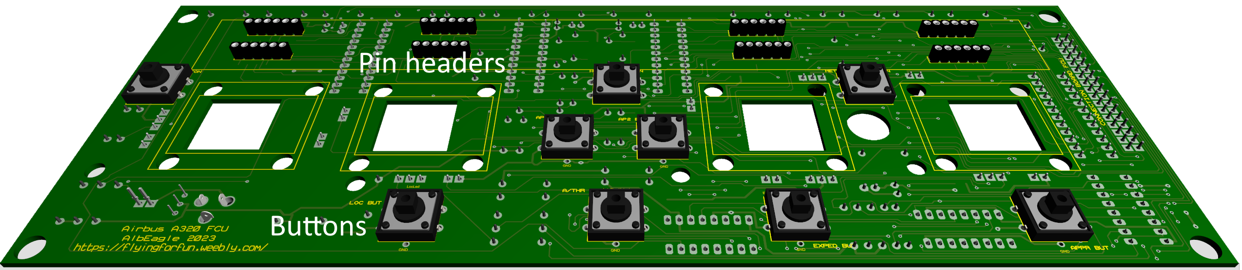
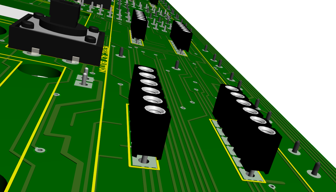
On the front side you can solder the tactile buttons and the pin headers for the displays. The pin headers are optional, but it is a good idea to use them. In case you have a faulty 7 segment display, you can switch them right away without any hassle. When soldering the pin headers, I recommend to solder them as high as possible, so the pins on the back of the pcb are at least flat with the pcb or slightly raised so you can solder them without issues. The reason for this is to raise the displays as high as possible, in order to have enough space to install the gears used for the banking switch.
|
|
The next step is to solder the LEDs. They should be positioned slightly lower than the displays. That's why I recommend to solder them after soldering the displays.
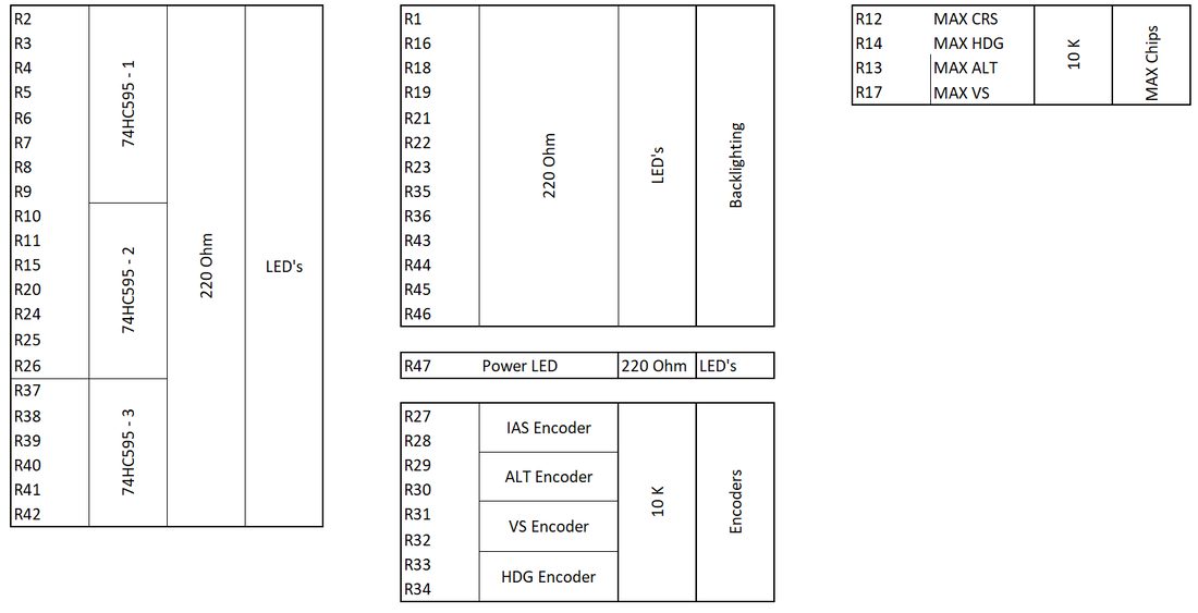
Resistors
Push/Pull encoder mounting
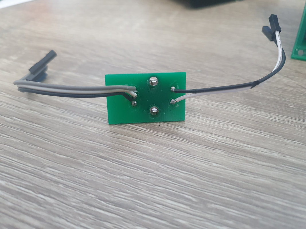
Solder the Encoders on the small encoder PCB's. Three wires for the encoder and two wires for the push button.
|
|
Than solder two wires on the small tactile push buttons (for the pull encoder function) and push them through the 3d printed encoder mount. you can glue the switch or just leave it free, it will be a tight fit and won't move anyway.
|
|
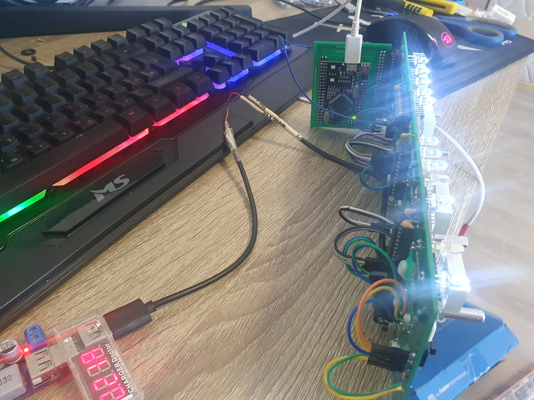
Than put the push the wires through the holes and insert the 3d printed mount together with the micro switch and encoder in it, into the FCU holes. On the back you can tighten them with the 3d printed nuts, but I also used hot glue gun to secure them even better. Connect the wires on the back of the PCB to the corresponding pins. This way you will have the push/pull encoders.
|
|
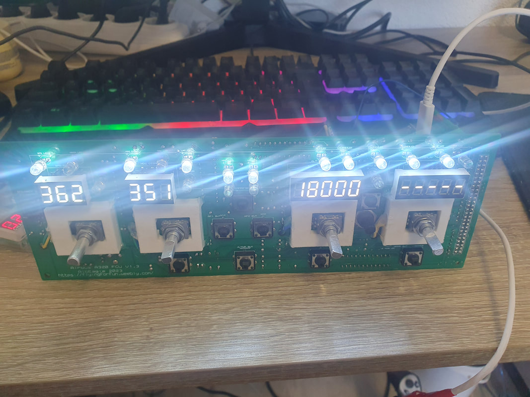
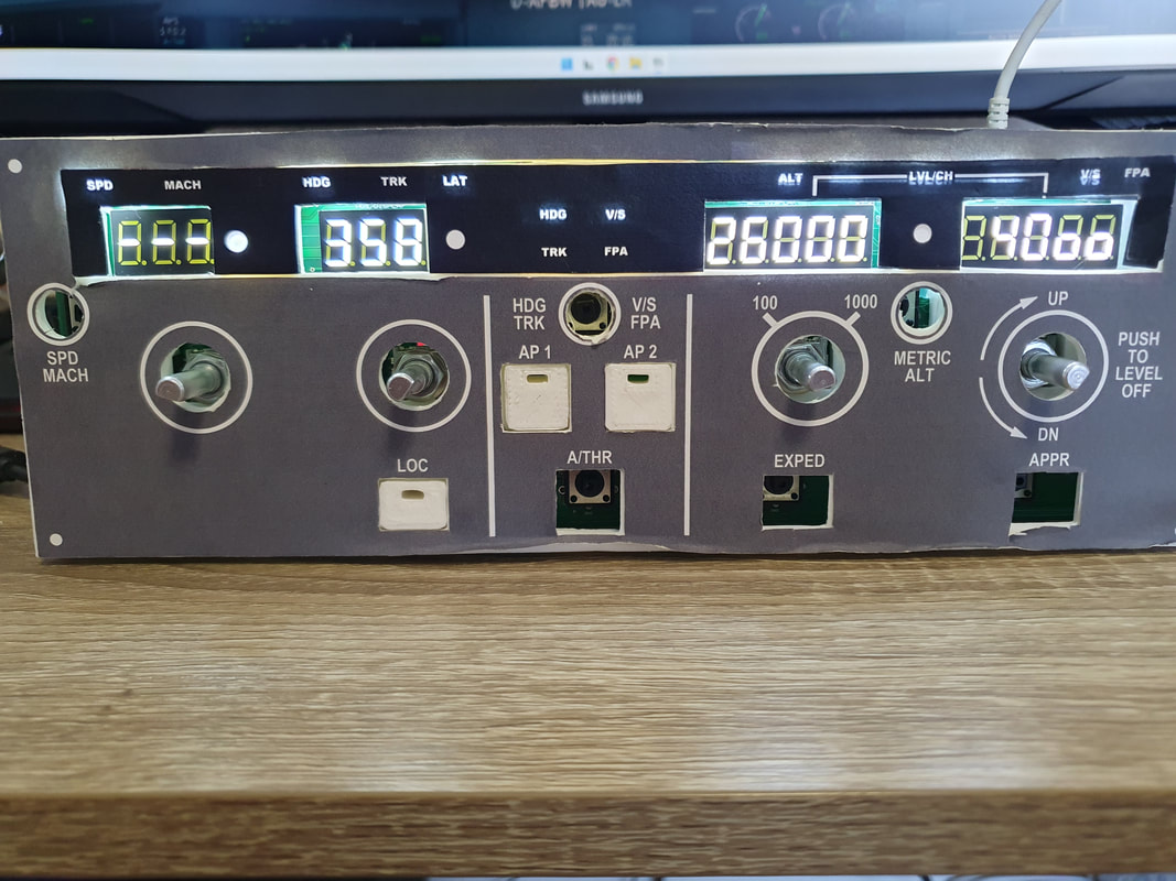
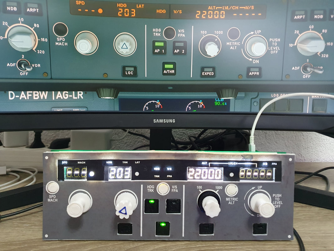
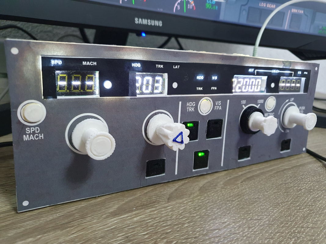
Using 3d printer is a bit difficult to make a great faceplate. I will be looking into cutting the faceplate from alucobond with a CNC, and then gluing good quality paper in front of it, since I don't own a laser cutter :(
|
|
|
|
|
Arduino PCB V1.3
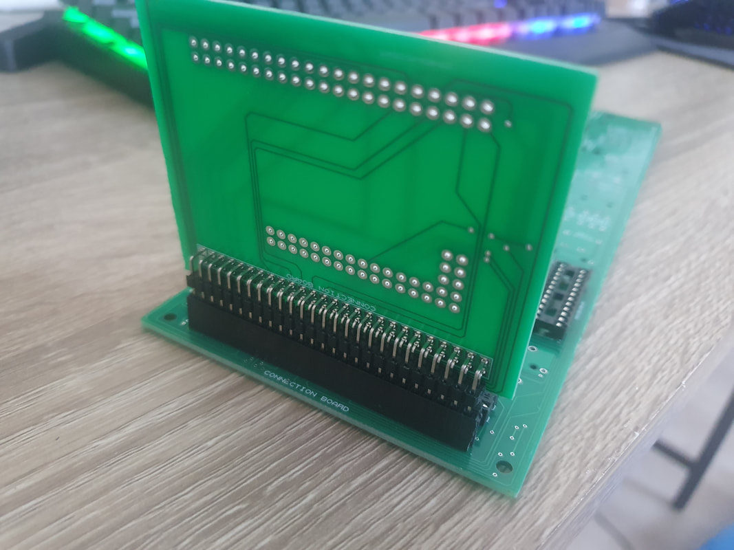
First you solder the female pins to the back of the FCU PCB.
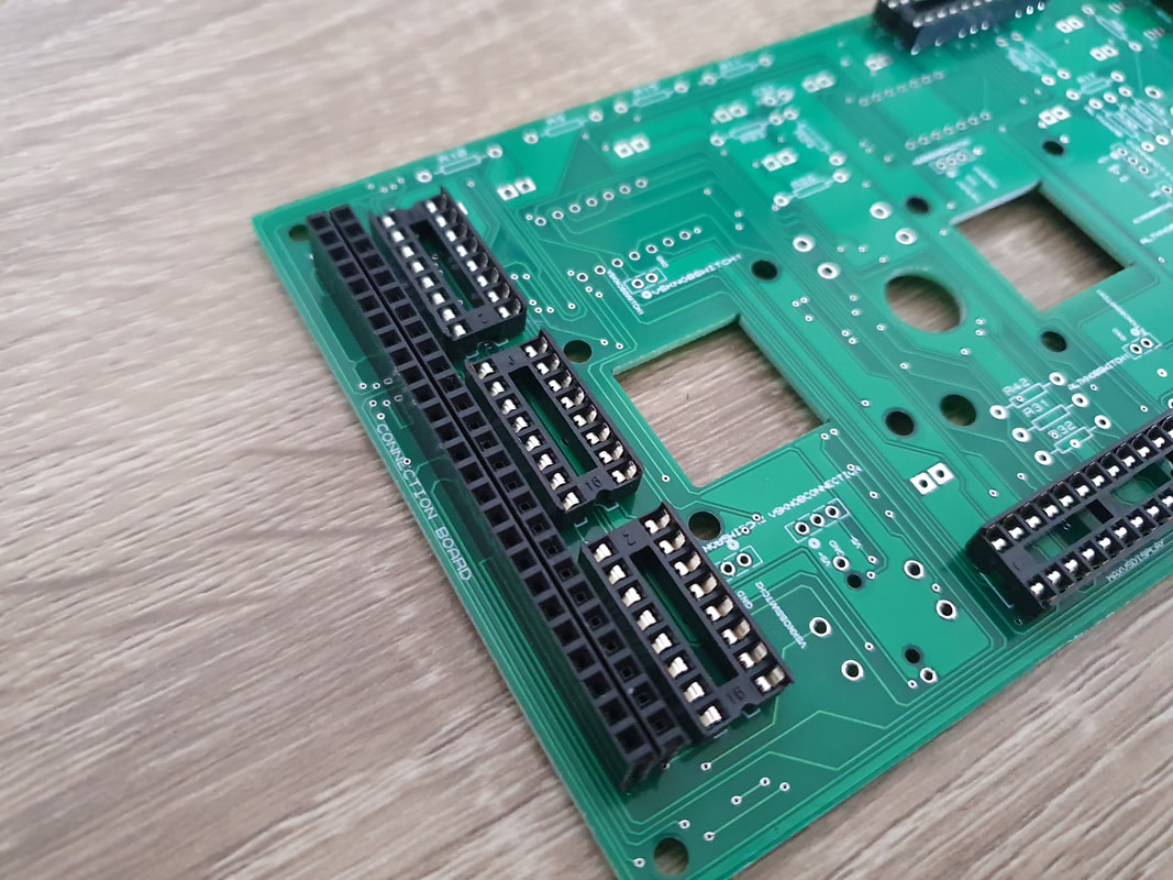
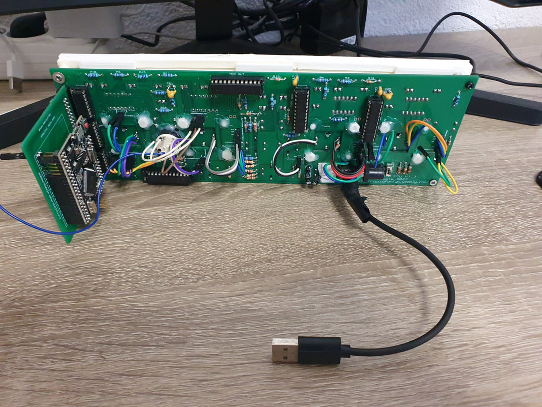
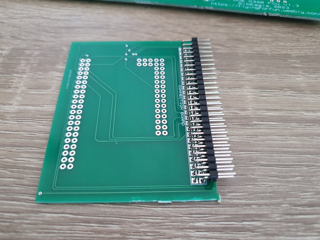
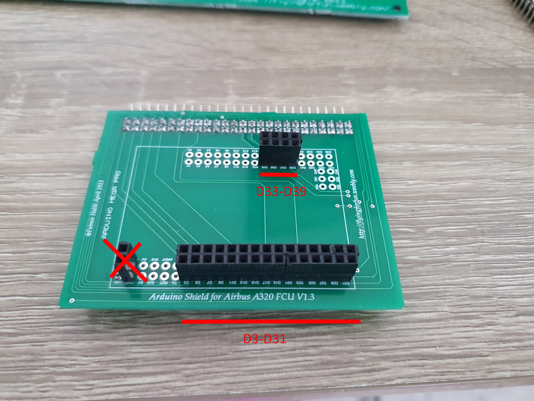
On the Arduino PCB, you need to solder the 90 degrees pins on the back of it as well. On the front side of the Arduino PCB you solder the female pins like in the picture below as those are the pins needed for the FCU. You can use the rest of the Arduino unused pins for other projects or modules. Ignore the pins marked with X sign as those are not needed in V1.6 (which is the latest version). it was only needed in V1.3 because the GND was not properly connected by the program so I had to manually wire it.
|
|
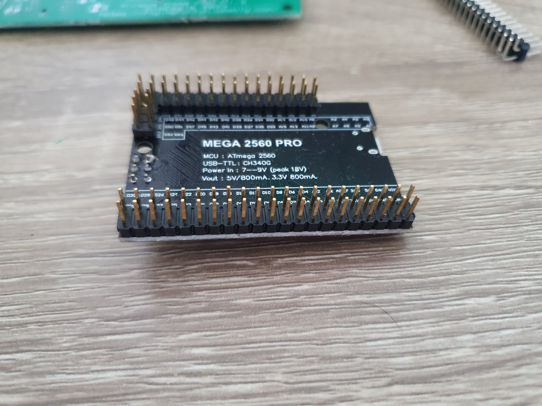
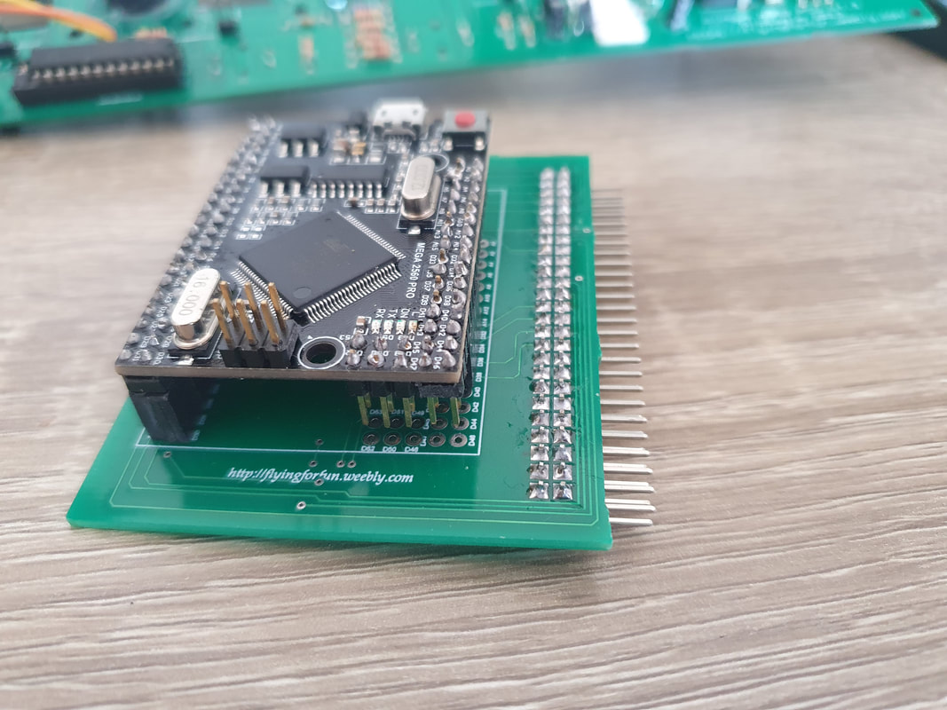
On the Arduino Mega 2560 Pro you can solder the pins that come with it on the back as shown in the picture, this way you can attach and detach the Arduino on the Arduino PCB easily, in case it gets damaged or in case you want to use the same Arduino on other projects.
|
|
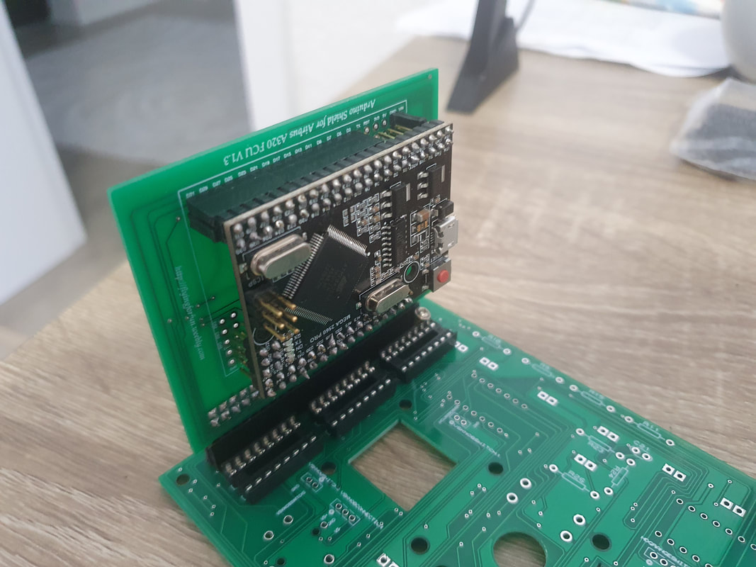
Once assembled, the Arduino PCB can be attached to the Airbus FCU using the pins, which is a convenient way.
|
|
Faceplate
|
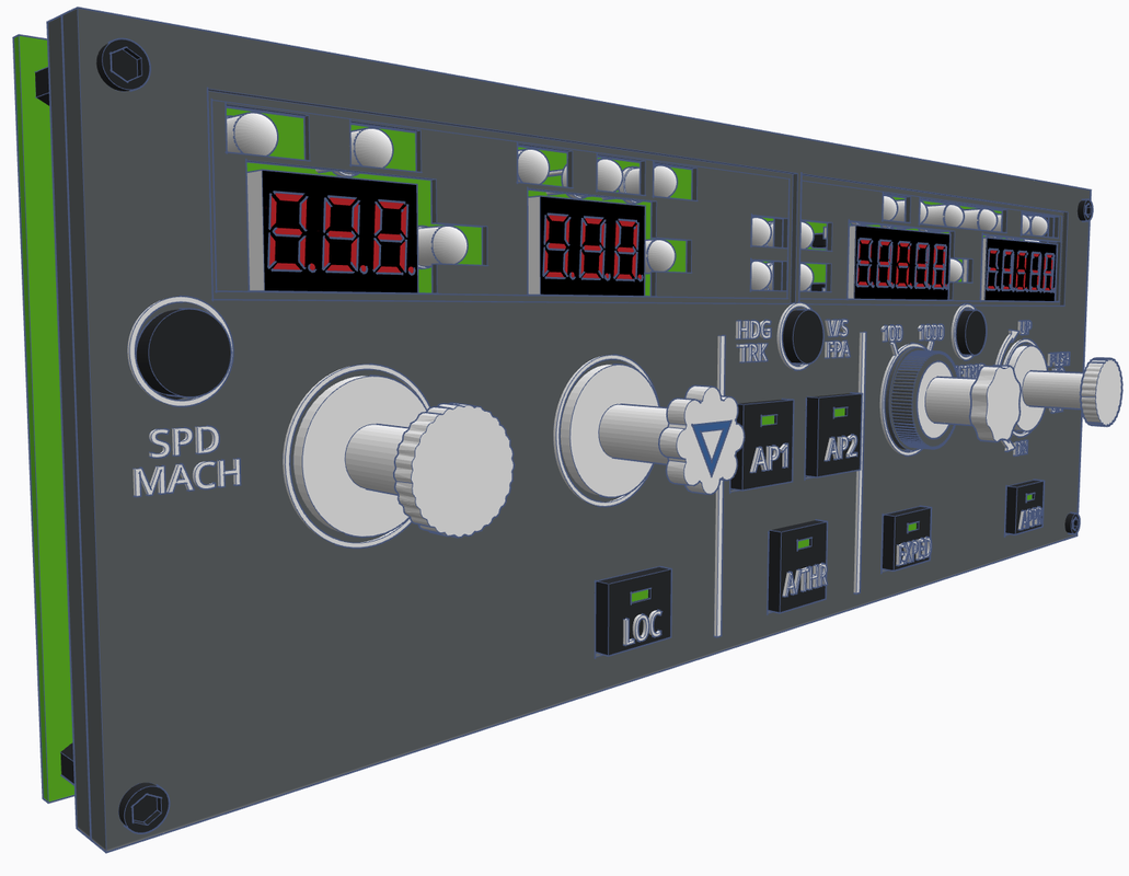
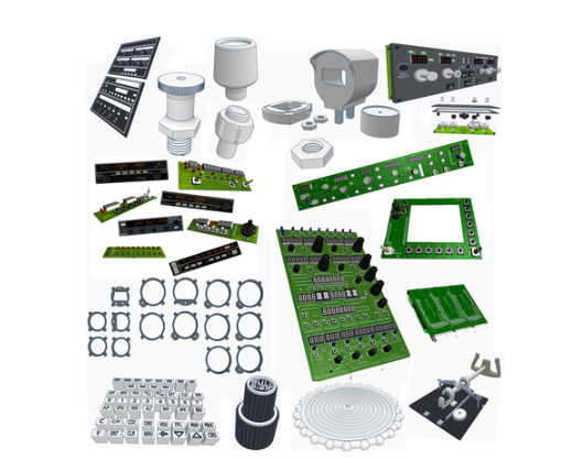
The best way would be laser engraving (or resin 3d printing) the faceplate, but since I am not familiar and don't own a laser myself neither do I own a resin 3D printer, I am designing the parts for normal 3d printing which is more difficult to achieve the desired look. Adding here also the different types of printers and printer settings.
The text should be printed with 0.2mm Nozzle. |
|
|
|
Pinouts
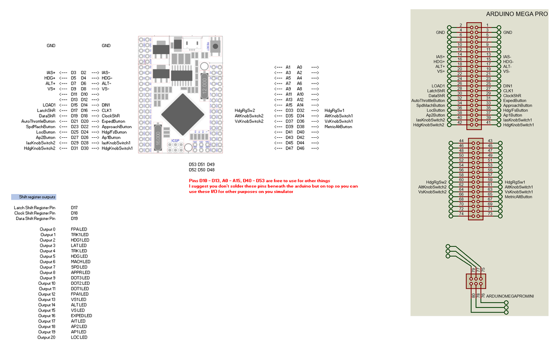

| Airbus_A320_FCU_V1.6_Pinouts.xlsx |
BOM
2015, Copyright AlbEAGLE